
Tools required:
- 110V--48V DC power supply (with current display) × 1
- Signal generator × 1
- Handheld power meter × 1
- Constant temperature soldering station × 1
- Oscilloscope×1, Brian has it
- Small Phillips screwdriver x 1
- Tweezers x 1
- Graphite tiles x 1
- Laser goggles x 1
Accessories needed for the full process:
- Devices with different capacitance values (20 each of 2pf, 4pf, 6pf, 8pf, 10pf)
- Fragile marking stickers × N
- 100MHz electronic devices×100
Inspection, replacement and testing processes:
Part 1: How to judge if No Beam is Due to 100MHz Oscillator Failure
Checking according to below article first: /knowledge/the-rf-tube-won-t-fire-the-beam#Problem_Description
After checking all the items in the article, still no beam, send the tube back to repair.
Checking process:
-
Use the signal generator to test if the RF tube has beam.
How to use the signal generator — video link:Place the graphite brick 50cm away from the laser beam outlet and fix it to make sure that when the beam comes out, the laser is emitted to the graphite brick.
If no beam, go to the next step. Goggles should be worn during the test.
-
Remove all screws on the top cover.
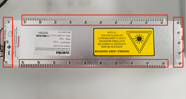
-
Find the 100MHz oscillator.
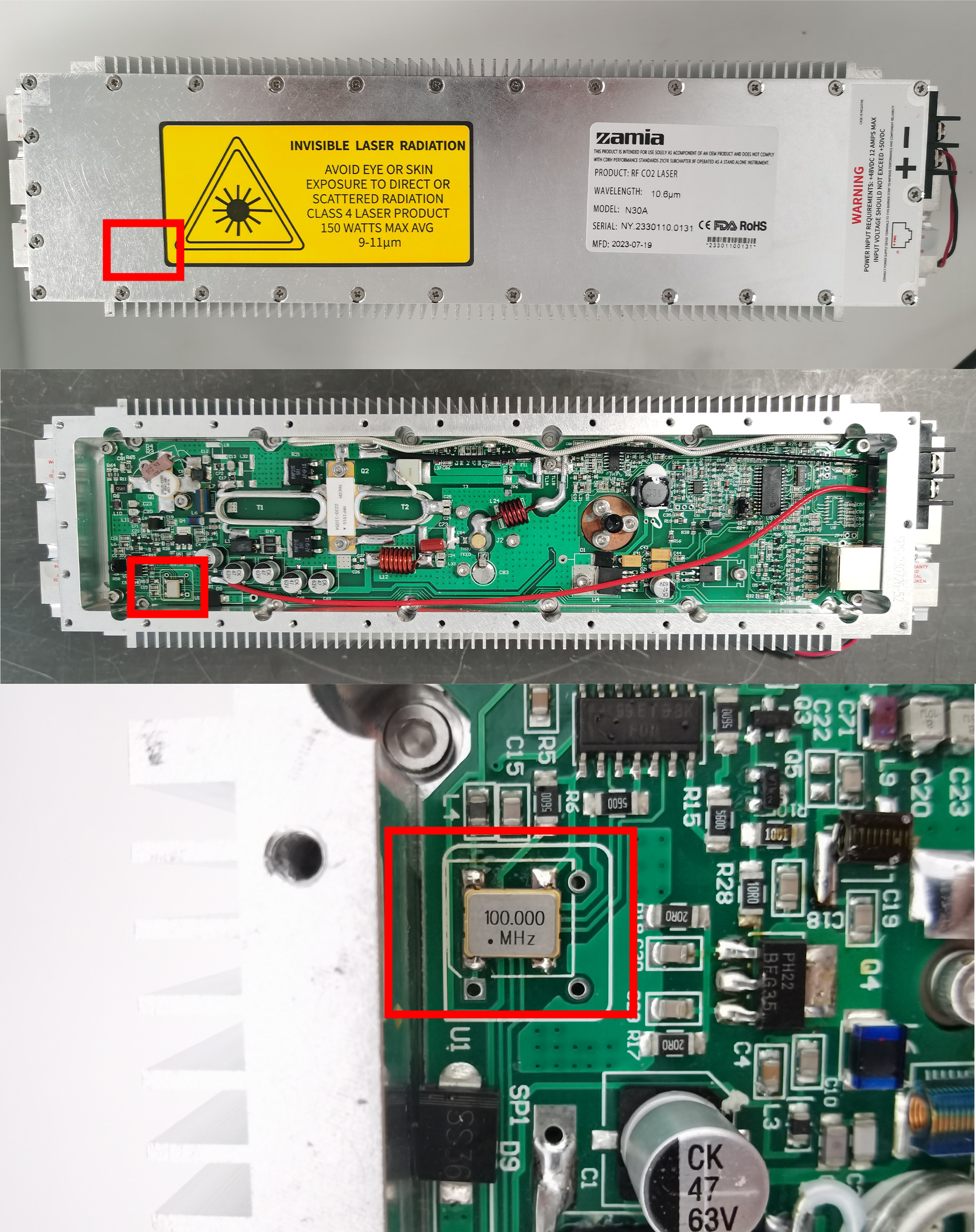
If the 100MHz oscillator looks like below, this indicates that the oscillator is good. Please install the top cover back on and proceed to Part 2.

If the 100MHz oscillator looks like below, which means the oscillator might be a wrong one (3.3V instead of 5V). Go to Step 4.

-
Check if the 100MHz oscillator is 3.3V or 5V.
a. With an oscilloscope
Use the oscilloscope to measure the signal at the output of the 100MHz oscillator:
If the screen shows like below, indicating that 100MHz oscillator is 3.3V — Go to Part 3.

If the screen shows like below, it indicates that the 100MHz oscillator is 5V. Go to Part 2.

b. Without oscilloscope
Replacing the 100MHz directly and go to Part 3.
Part 2: If the 100MHz oscillator is the correct one, then how we repair the tube
-
If the 100MHz oscillator is the correct one (5V), which means something else is failure. Replace whole RF module directly.

How to replace the whole RF module, video link:
-
Power the RF tube and wait 42s, then use 10% power to emit laser beam (make sure that the laser beam is emitted to the graphite brick, and you need to wear goggles during the whole process). And observe the current on 48V power supply.
Check if the current is within the following range, if so, go to step 3.
If no beam, it's a RF cavity failure, keep the faulty tube first.
10%, 1.9A–2.1A--需要再重新确认
If not in this range:
a. Less than 1.9A, remove the top cover.

Find the C83 capacitor, check the capacitor value.


How to judge the capacitor value. Just check the numbers and ignore the letters.

Judge method: If the current is less than 1.9A, replace the current C83 capacitor with a small value capacitor.
If it's a 4pf capacitor, replace it with a 2pf capacitor.How to replace the C83 capacitor, video link:
b. If the current is higher than 2.1A, replace the current C83 capacitor with a large value capacitor.
If it's a 4pf capacitor, replace it with a 6, 8 or 10pf.How to replace the C83 capacitor, video link:
Install the top cover back after replacing the C83 capacitor.
-
Use 100% power to emit laser beam (make sure that the laser beam is emitted to the graphite brick, and you need to wear goggles during the whole process). And observe the current on 48V power supply.
Check if the current is within the following range, if so, go to step 4.
100%, 10A–10.5A---需要再确认
If not in this range:
a. If it's a 4pf capacitor, replace it with a 2pf capacitor.
How to replace the C83 capacitor, video link:
b. If the current is higher than 10.5A, replace the current C83 capacitor with a large value capacitor.
If it's a 4pf capacitor, replace it with a 6, 8 or 10pf.How to replace the C83 capacitor, video link:
Install the top cover back after replacing the C83 capacitor.
-
Go Part 4.
Part 3: How to replace the 100MHz oscillator
A video for reference:
-
Use a hot air gun to melt the solder around the 100MHz oscillator to be replaced and then use tweezers to remove it.
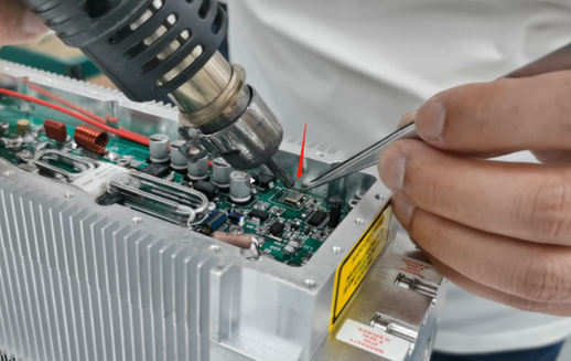
-
Hold the 100MHz oscillator with tweezers and put it back to the solder position. Install it according to below direction.

And please make sure the solder must not touch the yellow metal plate.

-
Install the top cover back after cooling. Go Part 4.
Part 4: Test the tube after repairing
-
Use the signal generator to use the 100% power output (to ensure that when the laser beam is emitted, the laser is emitted to the graphite brick) for 7 hours. The testing time can be accumulated, e.g. divided into 2 days, with 4 hours of aging on the first day and 3 hours on the second day.
Please pay attention to safety during the testing process and do not move the graphite bricks arbitrarily. Ensure that non-technical personnel stay away from the test area.
-
After the testing process is completed, use the signal generator to let the laser emit light at 100% power (make sure that the laser is emitted to the graphite brick when it emits beam, and wear goggles during the testing of the beam emission process), and use the power meter to measure the power.
-
Record the value.
-
Paste fragile sticker on tube.
Still stuck?
No bots, no runaround. Talk to a U.S.-based laser tech who knows your machine inside out.