
TL-Timer V9.0
The size is 155X100mm:

Indicator light port
232 serial port
NOVA/Odin Port Description
1) Input Port Description
- ① Input 1: Laser pre-ionisation detection port interface;
- ② Input 2: Temperature detection; (for nova51&63, has two heat boards)
- ③ Input 3: Laser temperature detection interface;
- ④ Input 4: Control air assist with "Low volume";
- ⑤ Input 5: Control air assist with "High volume";
- ⑥ Input 6: Temperature detection;
- ⑦ Input 7: Laser supply voltage detection port
- ⑧ Input 8: Spare;
- ⑨ Input 9: Emergency stop control (moving system, X/Y/Z axes that all are powered by 36V power supply, laser power supply);
- ⑩ Input 10: Emergency stop control (moving system, the same as Input 9);
- ⑪ Input 11: Spare;
2) 24V Output Port Description
- ① Output 1: Control the green light of warning light; when the machine is not at work, it's green.
- ② Output 2: Control the red light of warning light; when the machine is working or getting around alarm message on lcd panel, the warning light turns red.
- ③ Output 3: Control exhaust fan; Delay shutdown is set to 30s (Factory default setting, change it if required);
- ④ Output 4: Control air assist with "Low volume"; Delay shutdown is set to 20s (Factory default settings, change it if required);
- ⑤ Output 5: Control air assist with "High volume"; Delay shutdown is set to 20s (Factory default settings, change it if required);
- ⑥ Output 6: Control the fire alarm system; When a high temp is detecting on working area, the alarm system will active, the warning light alarms and the machine stops working immediately;
- ⑦ Output 7: Control the power for rotary device;
- ⑧ Output 8: Control the chiller and laser source (NOVA), and fan control board (ODIN);
- ⑨ Output 9: Control the X/Y/Z axes and laser power supply's power.
- ⑩ Output 10: Used for led lamp, adjustable brightness;
- ⑪ Output 11: Spare;
3) 5V Output Port Description
- ① Output port 5V1: Control red dot pointer;
- ② Output port 5V2: Control the lamp of the reset button;
- ③ Output port 5V3: Spare;
- ④ Output port 5V4: Spare;
4) Indicator Light Extension Interface
- Auto: Spare; (in parallel with 5V2);
- ON: Control fan control board
- Green: Spare; (in parallel with OUT1)
- Red: Spare; (in parallel with OUT2)
5) 232 Serial Port
Communicate with controller board, show the working status of the accessories on the panel;
TTL: Spare;
6) P1 Interface
Connection of door sensor checking board
Aurora Port Description
1) Input Port Description
- ① Input port 1: Manual mode or automatic mode detection;
- ② Input port 2: Spare;
- ③ Input port 3: Spare;
- ④ Input port 4: Spare;
- ⑤ Input port 5: Spare;
- ⑥ Input port 6: Spare;
- ⑦ Input port 7: Detect the rotating shaft input;
- ⑧ Input port 8: Spare;
- ⑨ Input port 9: Spare;
- ⑩ Input port 10: Spare;
- ⑪ Input port 11: Spare;
2) 24V Output Port Description
- ① Output port 1: Control the green light of warning light; when the machine is not at work, it's green.
- ② Output port 2: Control the red light of warning light; when the machine is working, it's red;
- ③ Output port 3: Control the exhaust fan;
- ④ Output port 4: Spare;
- ⑤ Output port 5: Spare;
- ⑥ Output port 6: Control the led lamp, adjusting brightness;
- ⑦ Output port 7: Control the rotary;
- ⑧ Output port 8: Control the laser source;
- ⑨ Output port 9: Control the 15V, 24V and 36V power supply;
- ⑩ Output port 10: Spare;
- ⑪ Output port 11: Spare;
3) 5V Output Port Description
- ① Output 5V1: Detective the door status, transferring the signal to the automatic focus card and the controller;
- ② Output 5V2: Bypass the door sensor;
- ③ Output 5V3: Control the lamp of reset button, transferring a signal to the automatic focus board;
- ④ Output 5V4: Spare;
4) Indicator Light Extension Interface
- Auto: The panel indicator light red light, shows whether the front door is automatic or manual, press the Emergency stop indicator light off; (Parallel with 5V2)
- ON: Panel indicator light red light flashing, after starting and reset, the indicator light is often on, press the Emergency stop indicator light off;
- Greed: The panel indicator light green light, display standby status; (Parallel with OUT1)
- Red: The panel indicator light red light, display working status; (Parallel with OUT2)
5) 232 Serial Port
Spare;
TTL: Connection to the autofocus board, control of the indicator status by means of commands sent by the autofocus board;
6) P1 Interface
Connection to key mask
- ① ON button: Reset function;
- ② Fan button: Turn on the exhaust fan;
- ③ Light button: Adjust the brightness of the lamp;
- ④ Up and down button: Control the up and down movement of the Z-axis;
- ⑤ Door cover button: Control the movement of the door cover;
- ⑥ Auto focus button: Auto focus function;
- ⑦ Start button: Start working.
TL-Timer V9.4
(Version 9.3 will only be used on machines shipped in July 2023; version 9.4 will be standardized for machines shipped in August 2023, and the new version can directly replace the old version of TL-timing.)

Bolt Port Description
1) Input Port Description
- ① Input port 1: Spare;
- ② Input port 2: Spare;
- ③ Input port 3: Spare;
- ④ Input port 4: Spare;
- ⑤ Input port 5: Spare;
- ⑥ Input port 6: Temperature detection;
- ⑦ Input port 7: Spare;
-
⑧ Input port 8: Dual air assist system icon on shield panel;
IN8 on the TL board is shorted and feedback to the controller through the 232 serial port, allowing the panel to hide the blow icon.
-
⑨ Input port 9: Normally closed emergency stop switch;
Press the Emergency Stop button to close IN9, allowing OUT6, OUT8 and OUT9, to stop the 24V output, and transmitted to the controller via a 232 serial signal to cause the operator panel to issue a warning.
- ⑩ Input port 10: Normally closed emergency stop switch; and IN9 in parallel.
- ⑪ Input port 11: Spare;
2) 24V Output Port Description
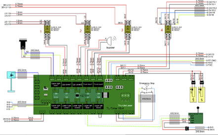
- ① Output port 1: Control the green light of warning light; when the machine is not at work, it's green
- ② Output port 2: Control the red light of warning light; when the machine at work, it's red; Red light flashes when door cover protection is on
- ③ Output port 3: Connecting the first relay to control the exhaust fan.
- ④ Output port 4: Spare;
- ⑤ Output port 5: Connecting the second relay to control the air pump;
- ⑥ Output port 6: Connect the buzzer; after triggering the temperature alarm, close IN6, OUT6 outputs 24V and turns on the buzzer.
- ⑦ Output port 7: Connect a third relay to control the 36V power input to the rotary unit
-
⑧ Output port 8: Output 24V to AC contactor, close contactor; energize 48V power supply and 36V power supply; (When the power-on reset is clicked on the operator panel, the signal is sent to the controller, which processes it to reset the X/Y axes, and after the reset is complete, it passes through RT-LINK to the 232 serial port on the TL board to make the OUT8 on the TL board output 24 V.)


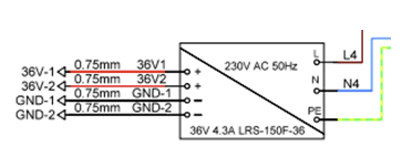
48V to power the FanCtrl board and laser;

36V to power the Z-axis driver and the Rotary Device.

- ⑨ Output port 9: Connect the fourth relay to control the 24V supply to the X/Y axis drive.
- ⑩ Output port 10: Control the left and right LEDs. Set brightness 20%-100% on the operation panel, OUT10 output 24V; set brightness 0%, OUT10 does not output 24V.
- ⑪ Output port 11: Spare;
3) 5V Output Port Description
- ① Output port 5V1: Control red light pointer;
- ② Output port 5V2: Spare;
- ③ Output port 5V3: Spare;
- ④ Output port 5V4: Spare;
4) Detect RF Tube Status Interface
Communicating with the FanCtrl board.
The laser status is feedback to the TL board via the FanCtrl board.

- Life led: Input voltage over 48V, always on
- Center led: RF Tube Temperature Alarm. (Poor heat dissipation can lead to high laser temperatures and laser malfunction, this led will always be on.)
- Right led: RF tube preheating, led is always on; preheating completed, led is always off.
5) 232 Serial Port
Communicate with controller board, show the working status of the some parts on the panel;
The 232 serial port on the TL board is connected to the RT-LINK on the controller
Signals transmitted via RTLink:
-
① Working status: small icons on the upper right corner of the screen.

-
② Standard and intelligent mode:
User can control the start or end delay time of exhaust and air assist. Switching the standard and intelligent mode.
- ③ Users can control the red light of red dot pointer.
- ④ Rotary connection detection.
- ⑤ Control the brightness of led lamp.
- ⑥ Emergency stop button detection, if it's been pressed, here is an alarm error on panel.
- ⑦ Flame alarm, if the heat sensor is triggered, here is an alarm error on panel.
- ⑧ Doors status detection.
- ⑨ Laser source status detection.
6) P1 Interface
Connection of door sensor checking board; Feedback of door cover status to TL control board
7) Three Buttons on the TL-Timing
- SET button: switches and manually controls OUT1-OUT7 outputs 24V.
- UP button: increases the delay time.
- DOWN button: reduces the delay time.
(Adjustable delay time for OUT3 and OUT5 24V outputs.
When the machine is energized, the set value of the Smart Mode on the operation panel is transmitted to the TL board through the controller, forcing the original value to be modified;
However, the values set by the TL board cannot be transmitted to the operator panel through the controller and modify its values.)


Still stuck?
No bots, no runaround. Talk to a U.S.-based laser tech who knows your machine inside out.