
Why Acceleration matters more than Top Speed when it comes to Raster Engraving
answer
Explains why increasing acceleration rate reduces raster engraving job time more effectively than increasing top speed, with real-world and theoretical test data.
Preface: This article will cover the differences in Acceleration and speed for a given engrave to highlight the time saved by changing a given parameter. Each type engrave will have different results, some will have better gains, some may have worse gains.
Is Peak Engraving Speed Really the Answer?
Everyone wants to talk SPEED as being the answer when acceleration rate is the key to reducing job time. Since an engrave requires extend space to allow the laser to speed up and slow down to turn around, that space is dead space and is completely dependent on the acceleration rate of the machine and engrave layer set speed. The faster your engraving layer set speed is, the larger your extend space is. On a stock NOVA, at 1000mms the extend space is over 2 inches per side, 4 inches total. So if you are engraving a 4" object, the total travel is over 50% extend space and over 8" wide. That is not very efficient especially since the extend space is where the machine is moving the slowest. The goal is to reduce the extend space, no matter the engraving layer set speed. In order to reduce the extend space, we need to increase the acceleration rate (deceleration rate too). The other discussion around speed should be centered around what speed do you normally engrave at and does your laser have the power to make meaningful marks at that speed. A lot of engraving is done under 1000mms, in the 600 and below range. Times where engraving is done at higher speeds can be attributed to sensitive materials, hot tubes, large basic engraves etc.
For More On Extend Space:
- Extend Space Required based on Engraving Layer Speed for stock Odin Series Machines
- Extend Space Required based on Engraving Layer Speed for stock NOVA series Lasers
Preview comparison in Lightburn 1000mms vs 1400mms on stock 1G Acceleration for a 4.7"x2.5" object:

1000mms yields at 3:13 estimate vs 1400mms yields at 3:54 estimate, a 21% increase in time when going 400mms faster
Preview comparison in Lightburn 1000mms vs 1400mms on stock 1G Acceleration for a 18.7"x10" object:

1000mms yields at 23:13 estimate vs 1400mms yields at 23:01 estimate, a .87% Decrease in time when going 400mms faster...not even 1 whole percent point for going 40% faster.
So in short, Speed is not always the answer, sometimes it is the problem. Note that on larger engraves and larger beds, speed can be more helpful since the ratio of Extend Space Width to Engraving Area width is reduced but, the faster you go, the smaller your bed gets due to extend space on both sides of the engrave area.
Preview comparison in Lightburn 1000mms vs 1400mms on modified 3G Acceleration for a 18.7"x10" object:
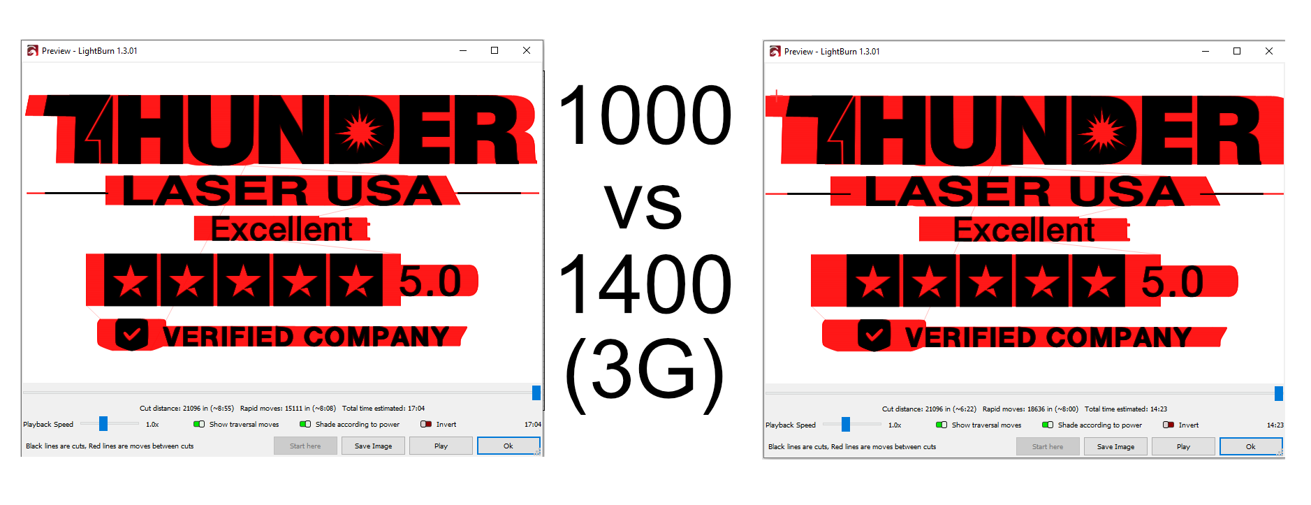
1000mms @3g yields at 17:04 estimate vs 1400mms yields at 14:23 estimate, a 15.73% Decrease in time when going 400mms faster with 3G Acceleration. Sounds good right? You went 40% faster to save 15.73% of the time? Still not great. Now lets compare the 3G time to the 1G times. Going from 3G from 1G accel, at 1000mms reduced the time from 23:13 to 17:04 and at 1400mms the time was reduced from 23:01 to 14:23. The 1000mms saw a 26.5% Decrease in time, the 1400mms saw a 37.5% Decrease.
Conclusion: Acceleration is the answer, to a point. Speed plays a roll here as well but with a DC excited glass CO2 tube...how fast can you really going before you cannot discern dots and they are no longer round? There is also a point of diminishing returns to acceleration rates as well, based on the peak speed of the laser. Read the rest of the article to see the testing results and more information.
The Test Setup
Stock Nova
A stock Nova 35 with 10000mms/s acceleration with a top speed limit set to 1000mms (capable of 1200mms) utilizing the stock motors and drive components which includes the Leadshine motor and driver. More information about the Leadshine Motor and Driver: Leadshine 573HBM20 Series EZ Servo
Note that the stock pulley on the Leadshine is a 20tooth pulley.
Vs What is changed
A Clearpath Servo with integrated driver with a 18 tooth pulley was swapped for the X axis. The Teknic Clearpath Servo used is a CPM-SDSK-2326P-RQN on the stock 36V power supply. Technical information is below:


Test Goals
The primary goal of this testing was to push the limits of the acceleration of a Nova Laser beyond the 10000mms/s (1G) and to probe all the way up to 50000mms/s (5G) Acceleration. Peak speed is not a goal but it will be tested to observe the limit of the Clearpath Servo on a Nova machine.
Clearpath Servo Configuration in MSP 2.0 software


Initial Testing Results
Offset Generation
Offsets were generated for the new motor setup and work from 1G to 5G acceleration:
Stock Offsets with Leadshine Motor:

Offsets with Clearpath Servo:
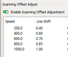
Much larger offsets required but showed a proportional relationship to the speed where as the Leadshine Stock motor settles to a lower offset at 1000mms generally.
Turn it up: 1G vs 2G vs 3G vs 4G vs 5G Acceleration
Sample Job Setup: 1000mms, .080 LPI, single pass with object ~ 4.7" x2 .5"

Sample job run at 1G (10000mms/s) Stock Acceleration: 3:08 to complete

Sample job run at 2G (20000mms/s) 2x Stock Acceleration: 2:08 to complete

Sample job run at 3G (30000mms/s) 3x Stock Acceleration: 1:49 to complete

Sample job run at 4G (40000mms/s) 4x Stock Acceleration: 1:42 to complete

Sample job run at 5G (50000mms/s) 5x Stock Acceleration: 1:40 to complete

Real world Results Comparison run on Nova 35

Using Lightburn Preview to obtain Theoretical Results
(Note that in Lightburn, a machine acceleration setting of 10000mms/s yields an uploaded value of 9250mms/s, 50000 is 46250 etc)

For the standard 4.7"x2.5" object:

For the a resized engrave of a 18.6"x10" object:

The above tables show that increasing the Engrave Object Size will minimize the impact of acceleration of the total overall job time but, that the improvement between each step of 10k acceleration value holds to be about the same. The total reduction in completion time for the job has diminishing returns compared to increasing the acceleration rate by 10000mms/s, meaning you do not gain the same time reduction rate as you keep increasing the acceleration rate.
Peak Speed Testing
Probed to 1800mms/s and a position error was generated for being over 200 counts. At 1600, the position error was around 100 counts which is 1/8th a shaft revolution. For now, the peak useful engraving speed will be left at 1200mms.
Theoretical Speed and Acceleration Comparison
Using the Lightburn built in time estimation (it was fairly accurate and showed the same trends as the real world testing), we can create some tables and heat maps showing the affect of increasing the Engraving Layer Speed and the X axis Acceleration rate. In the tables below you can see the time estimation and then the relationship of how long the other Engraving Layer Speed Settings took to complete as compared to the base speed of 1000mms.
Estimator Output time for a set Speed and Set Accel rate:
(note that Lightburn as a .925 multiplier on the machine setting for X axis accel rate rate when doing the estimation)
What is interesting about the above graph is how the "Time to Complete" actually increases as you increase the speed above 1000mms when the machine acceleration rate is set to 10000mms/s. To more easily see that, check out the table below:

The best combinations of Gains are in the 1200mms column, even when maxing out the acceleration to 50000mms/s.
Still stuck?
No bots, no runaround. Talk to a U.S.-based laser tech who knows your machine inside out.