
AccuMetal Electrical Cabinet — Parts and Functions
AccuMetal 24, 1.5 kW, 240 V single-phase · rear cabinet, doors open · Thunder Laser USA · Nov 10, 2026 · rev 3
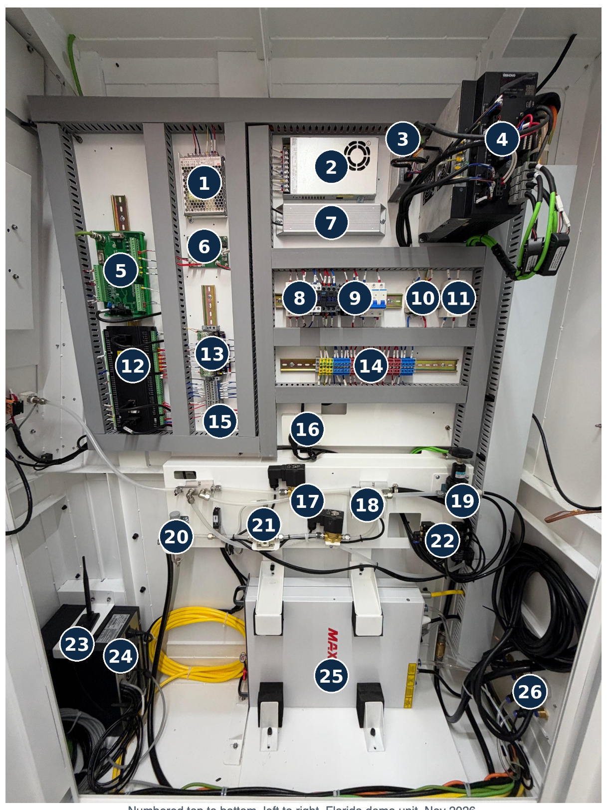
Numbered top to bottom, left to right. Florida demo unit, Nov 2026.
Parts list
| # | Part | What it does | Customer |
|---|---|---|---|
| 1 | Mean Well LRS-100-48 power supply | 48 V, 2.3 A. Powers the focus-motor drive (3) and the cutting head's motorized focus. Separate from the 24 V control supply. | No |
| 2 | Main 24 V power supply (fan-cooled) | Switch-mode supply for the whole 24 V control side: controller, I/O, relays, sensors, solenoids. The fan must run; if it stops, the control side overheats. | No |
| 3 | Leadshine EC503 EtherCAT stepper drive | Drives the cutting head's focus motor. Sits on the EtherCAT chain with the servo drives. ERR / RUN / L/A lights on the front. If autofocus stops moving, start here. | No |
| 4 | Weihong M4 EtherCAT servo drives, 1.0 kW (×3) + 400 W Z | One drive per motor: X, two on Y, Z with brake. Take 240 V in, drive the servos, talk to the controller over EtherCAT (green cables, IN/OUT). Status LED on each; an alarm code here is the first thing to read on a motion fault. | No |
| 5 | Weihong I/O terminal board | Breaks the controller's inputs and outputs out to field wiring: limit switches, door interlocks, E-stop loop, gas valves, lights. DB connector to the controller, screw terminals to the machine. | No |
| 6 | Thunder fan-control board | Thunder Laser's own board. Slide switch sets the enclosure fans to Quiet or Max Power; buzzer and RJ45 link. Spares come from Thunder Laser USA, not Weihong. | Yes: switch |
| 7 | Braking resistor | Finned aluminum block. Absorbs energy from the servos when the gantry decelerates at 2 G. Hot in normal use; keep clear. | No |
| 8 | Circuit breakers: CHNT NXB-63 C50 (3-pole main), NXB-63 C32 (2-pole branch) | The C50 is the machine main; the C32 feeds a branch (laser source / servo bus). A tripped handle sits mid-position. Reset once; if it trips again, stop and call. Repeated C32 trips point at the source or a drive. | Yes: reset once |
| 9 | Contactors: CHNT NXC-18 (×2), CJX2-1810 | Connect 240 V to the servos and the laser source when the controller says the machine is safe. Drop out on E-stop and door-open. You hear them clunk at power-up and again when the laser is enabled. | No |
| 10 | EMI line filter CW4L2-32A-S | Keeps drive and laser noise off your shop power, and shop noise off the machine. Depends on a good cabinet earth bond. | No |
| 11 | Sinoya voltage protector | Upper display is incoming line voltage (246 V in the closeup). Trips the machine if supply sags or surges outside its window. Under ~210 V or over ~250 V under load is a shop-power problem, not a machine fault. Buttons set the limits; leave at factory. | Yes: read only |
| 12 | Weihong Lambda 21E EtherCAT controller | The brain. Runs the NcStudio 2000M control: takes the program from the PC and commands the drives, laser, gas valves and height follower over EtherCAT. POWER and SYSTEM lights on the label. Never power-cycle it with the PC running. | No |
| 13 | Interposing relays (×4) | DIN relays with blue clips. Controller outputs switch these; the relays switch the real loads: contactors, blower, chiller enable, lamp. Relay clicks but the load doesn't run: look at the load side. | No |
| 14 | Power distribution terminals | Green-yellow = earth, blue = neutral, red = live, gray = switched. The incoming feed lands here and fans out to the breakers. Torque-check yearly. | No |
| 15 | Control terminal strip | Gray DIN terminals, numbered. Every control-side wire lands here; the wiring diagram references these numbers. | No |
| 16 | Auxiliary outlets (×2) | Switched 240 V outlets inside the cabinet. Feed the exhaust blower and chiller enable so they run with the machine. | No |
| 17 | Gas-selection solenoid valves | Black-coil valves. The controller opens air, oxygen or nitrogen depending on the layer in the program. Sticking valve = wrong gas or no gas. Listen for the click when a job starts. | No |
| 18 | AirTAC PK510 pressure switch | Mechanical pressure switch, auto reset. Confirms the gas supply is actually up to pressure before a pierce. Set point on the dial; leave at factory. | No |
| 19 | Clamp air regulator and gauge | Sets the air supply to the pneumatic sheet clamps and door cylinder. Not the cutting gas. Clamps always run on air regardless of cutting gas. | Yes |
| 20 | Air filter / regulator, shop-air inlet | First stop for shop air. Traps water and oil and sets the pneumatic working pressure. Drain the bowl daily in humid weather; a wet bowl means the dryer isn't keeping up. | Yes |
| 21 | NNT NITV2050-312L electronic proportional regulator | The controller sends 0–10 V and this sets assist-gas pressure, 0.005–0.9 MPa (to ~130 psi), per layer: cutting and piercing pressure. The red display is the live pressure the head gets; it is the number on the screen. | Yes: read only |
| 22 | Pneumatic valve manifold | Small solenoid bank. Operates the thin-sheet clamps, pressure bar and any pneumatic door or lube functions. | No |
| 23 | Industrial PC: YH350D-I5, 220 V 300 W, Wi-Fi | Runs NcStudio and the 21.5 in display. The antennas are its Wi-Fi. Shut down from Windows before cutting power or NcStudio parameters can corrupt. | Yes: shutdown |
| 24 | Auxiliary module (gray, labeled) | Small boxed module beside the PC. By position, the laser alarm/safety relay or the chiller-flow interface. Confirm from the factory wiring diagram. | No |
| 25 | MAX Photonics fiber laser source, 1.5 kW | Generates the beam. Water-cooled by the chiller's low-temperature circuit. Enabled by the contactors and the controller; interlocked to doors and E-stop. Keep the vents clear. Back-reflection protection lives here; see the KB for the unlock procedure. The armored cable coiled at right is the output fiber: never tighten the coil, hang anything on it, or kink it. | No |
| 26 | Gas inlet bulkheads | Brass fittings with push-in ports on the cabinet wall. Shop air, oxygen and nitrogen connect here from outside. Labeled; do not swap. | Yes: connect |
Closeups
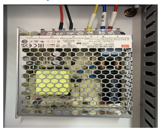
1 · Mean Well LRS-100-48 power supply
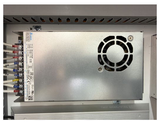
2 · Main 24 V power supply (fan-cooled)
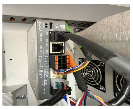
3 · Leadshine EC503 EtherCAT stepper drive
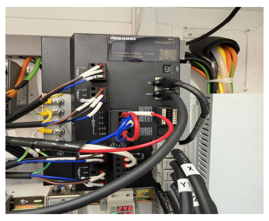
4 · Weihong M4 EtherCAT servo drives
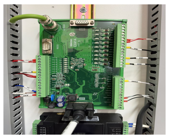
5 · Weihong I/O terminal board
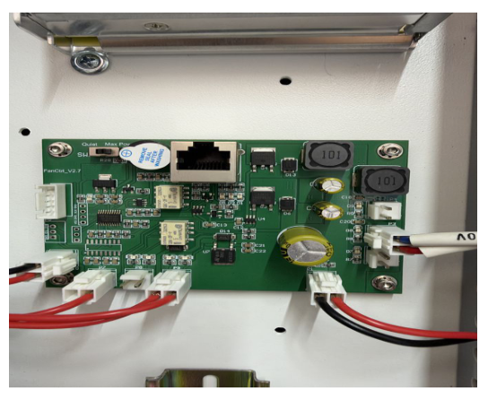
6 · Thunder fan-control board
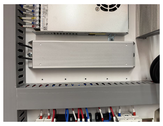
7 · Braking resistor
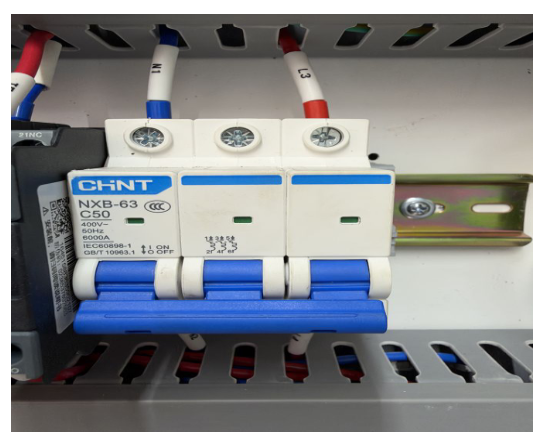
8 · Circuit breakers
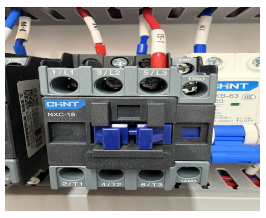
9 · Contactors
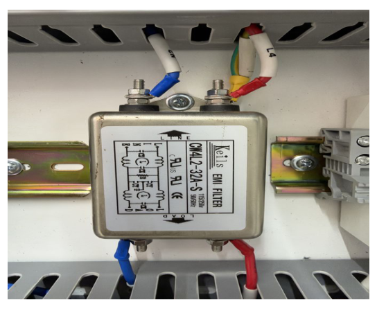
10 · EMI line filter CW4L2-32A-S
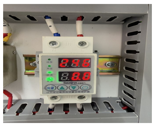
11 · Sinoya voltage protector
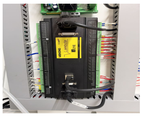
12 · Weihong Lambda 21E EtherCAT controller
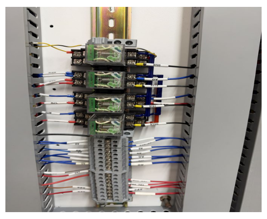
13 · Interposing relays (×4)
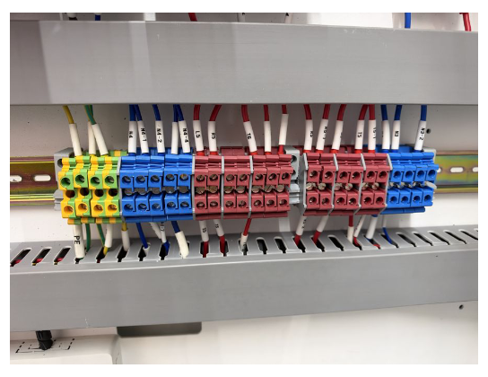
14 · Power distribution terminals
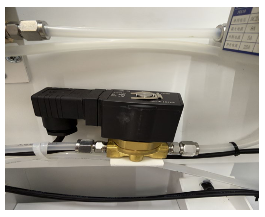
17 · Gas-selection solenoid valves
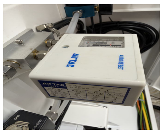
18 · AirTAC PK510 pressure switch
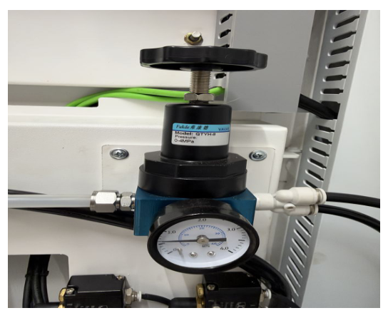
19 · Clamp air regulator and gauge
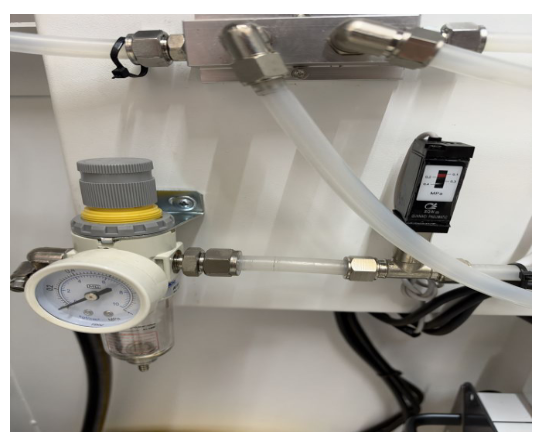
20 · Air filter / regulator
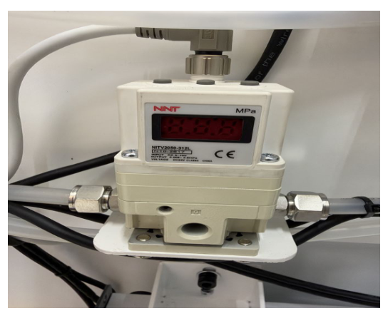
21 · NNT NITV2050-312L electronic proportional regulator
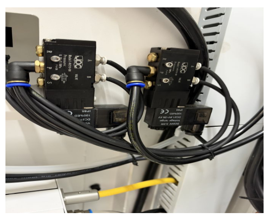
22 · Pneumatic valve manifold
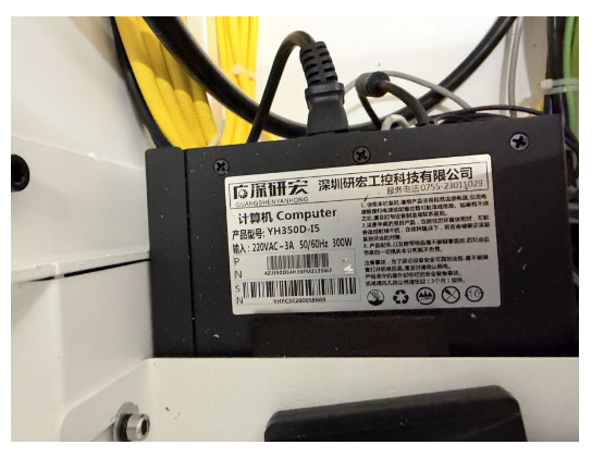
23 · Industrial PC
What a customer may do in this cabinet
- Read the voltage protector (11) and the gas pressure display (21).
- Reset a tripped breaker (8) once. If it trips again, stop.
- Drain the air filter bowl (20); set clamp pressure (19).
- Connect gas lines at the bulkheads (26).
- Flip the fan board switch (6) between Quiet and Max Power.
- Shut the PC (23) down from Windows before cutting power.
Everything else is a Thunder Laser USA technician's job or a guided call. Opening the fiber source or disconnecting the fiber voids the source warranty.
First things to check on a fault
| Symptom | Look at |
|---|---|
| Machine dead, screen on | Breakers (8) · voltage protector (11) · E-stop and door loop at the I/O board (5) |
| Axis alarm / autofocus dead | Drive LEDs (4) · EC503 ERR light (3) · 48 V supply (1) · braking resistor hot? (7) |
| Laser won't fire, motion fine | Source contactor pulled in? (9) · chiller alarm at (24) · source status LEDs (25) |
| No gas / wrong gas | Solenoid click (17) · pressure display (21) · pressure switch (18) · bulkhead (26) · inlet regulator (20) |
| Clamps don't grip | Clamp regulator (19) · manifold (22) · filter bowl (20) |
| Screen frozen / no network | PC (23) · Lambda SYSTEM light (12) |
Parts identified from nameplate photos of the Florida demo unit, Nov 2026. Item 24 still needs the factory wiring diagram. Add BOM part numbers before customer release.
Still stuck?
Fastest response times in the industry from our US-based support team.