
Preface
As of June 2026, the Thunder Air 700 fume extractor supports linkage control with Thunder laser machines via a signal cable. The extractor can automatically start and stop together with the laser machine, with support for pre-start and delayed shutdown functions. The control logic is consistent with the standard Thunder exhaust fan system and is designed to reduce energy consumption, minimize operating noise, avoid unnecessary filter wear caused by idle running, and extend filter service life.
Note: Currently, alarm pop-up notifications are displayed only on the fume extractor's control panel and cannot yet be synchronized to the laser machine's panel. Please regularly check the extractor's operating status and filter condition, perform maintenance in a timely manner, and replace filters when necessary to ensure effective fume filtration.
This document describes two connection methods for the signal cable.
Choose the appropriate method according to whether your laser machine is equipped with a DB9 signal port.
1. New Thunder Laser Machines (with built-in DB9 fume extractor signal port)
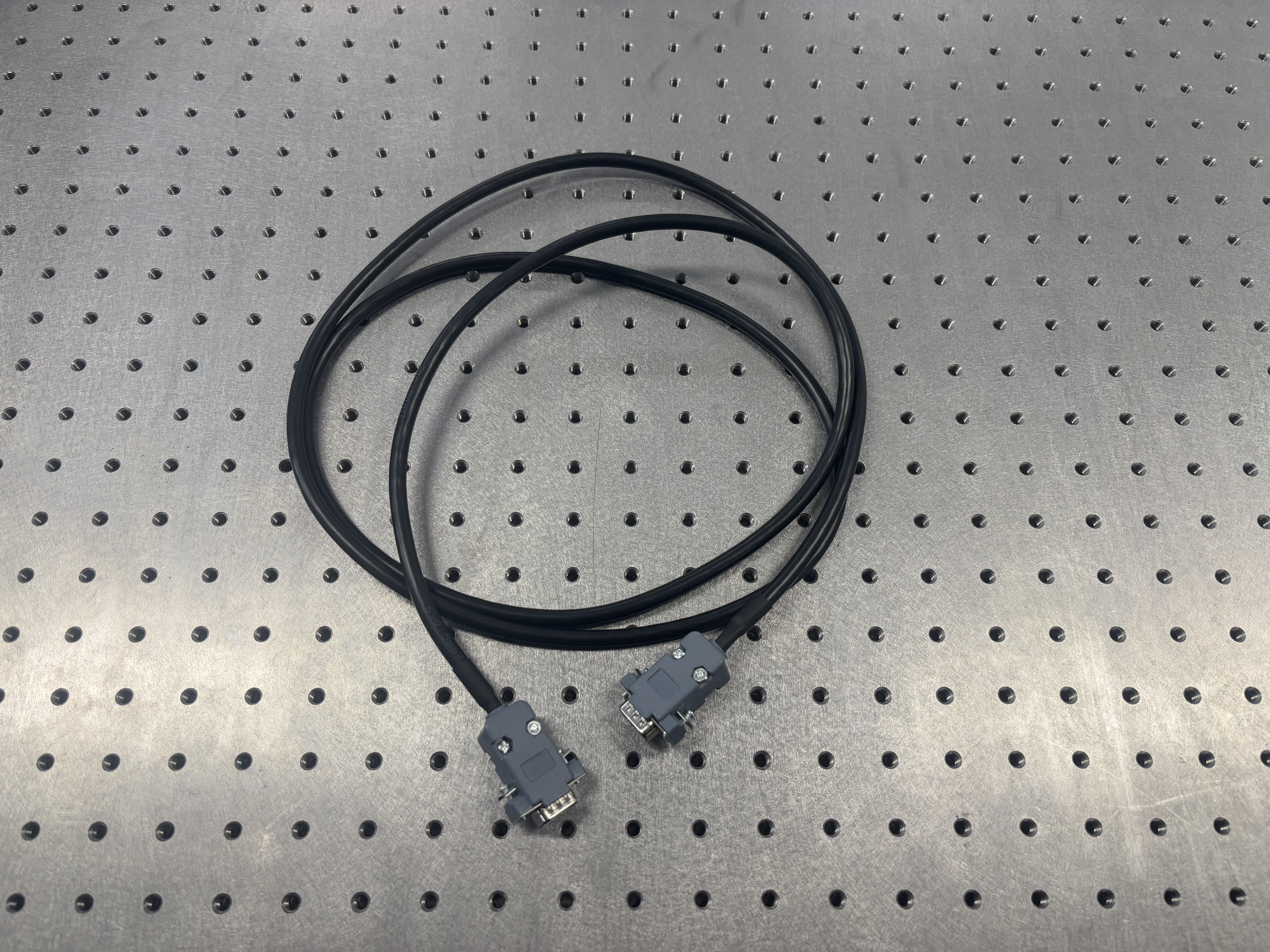
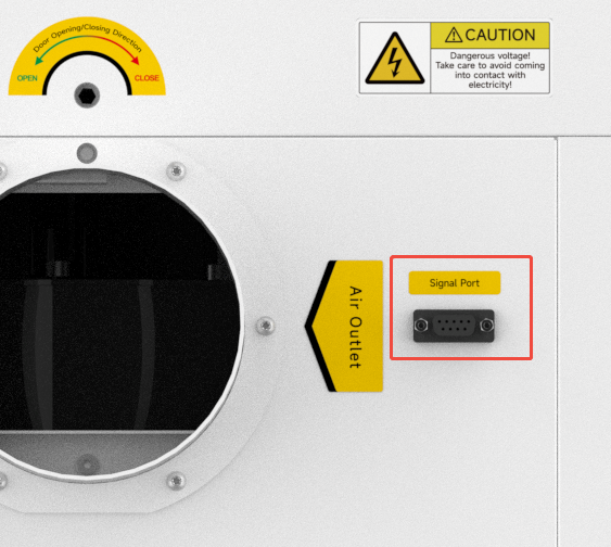
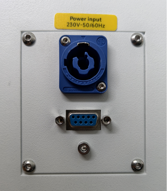
Use the signal cable supplied with the fume extractor to establish communication between the laser machine and the extractor.
| Signal Cable | Interface on the fume extractor | Interface on the machine |
|---|---|---|
 |
 |
 |
2. Existing Thunder Machines (without a dedicated DB9 fume extractor signal port)
Introduction
Current versions of Thunder engraving machines do not include a dedicated signal port for the fume extractor. Therefore, the supplied signal cable must be modified and connected to the spare relay terminals used for fan start/stop control, allowing the laser machine and extractor to operate in linkage mode.
Operating Procedure
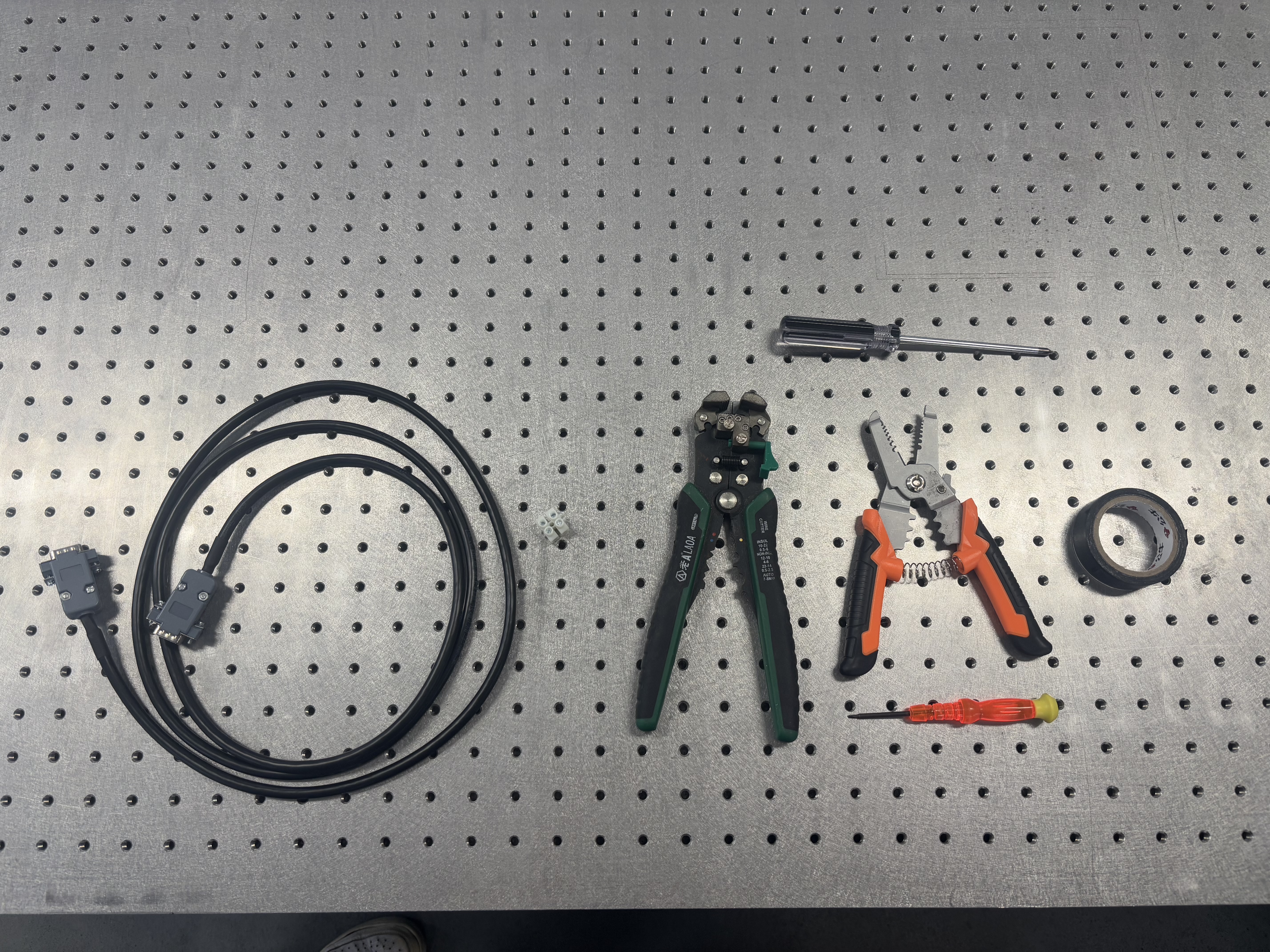
2.1 Remove the DB9 connector from one end of the signal cable and use the two functional wires inside.
|
Tools required
|
 |
| 1. Open the DB9 connector at one end of the cable and remove the housing to expose the soldered pins. | 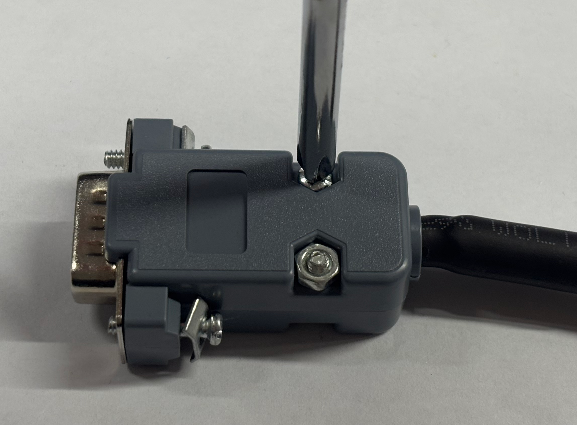 |
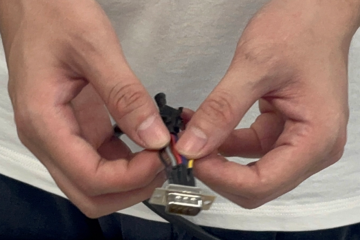
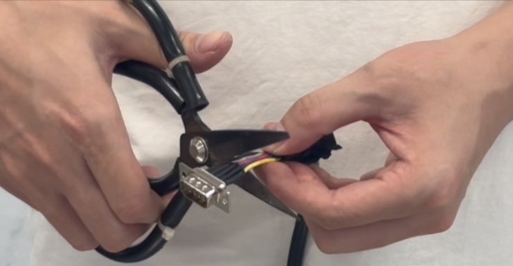
| 2. Locate the leftmost and rightmost wires in the 5-pin row, mark them, and then cut off the DB9 connector. |
|
| 3. Keep the two marked wires, trim the remaining wires short and insulate them with electrical tape. | 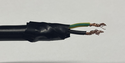 |
| Note: Due to different manufacturing batches, some cables may already contain only two conductors. In this case, simply remove the DB9 housing and proceed to the next step. | 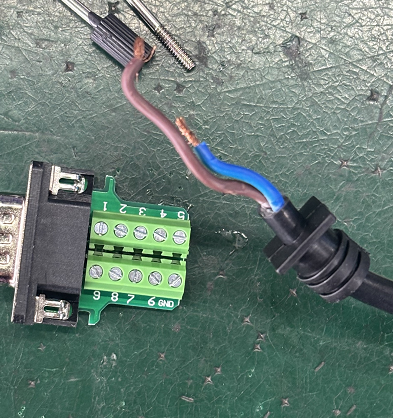 |
| 4. Strip the insulation from the selected wires to expose the metal conductors. If available, you may crimp terminals onto the wires, which will make relay connection easier. | 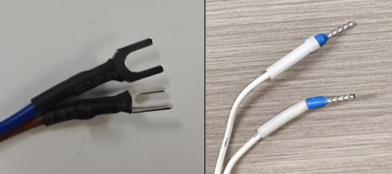 |
2.2 Connect the two prepared wires to the spare terminals of the relay that has the wire labeled "L6". This will enable normal linkage control between the laser machine and the fume extractor.
| Connect the two wires to the machine relay | 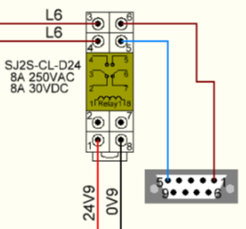 |
|---|---|
| TITAN: | 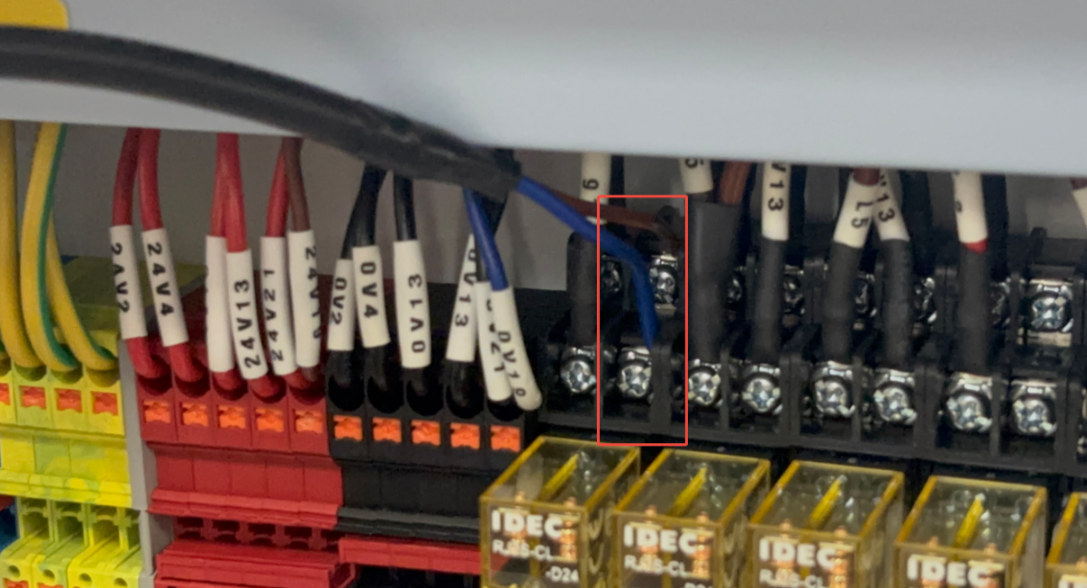 |
| BOLT: | 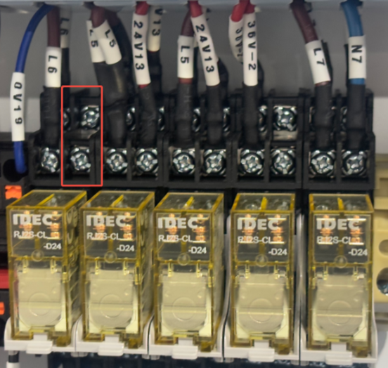 |
| NOVA: | 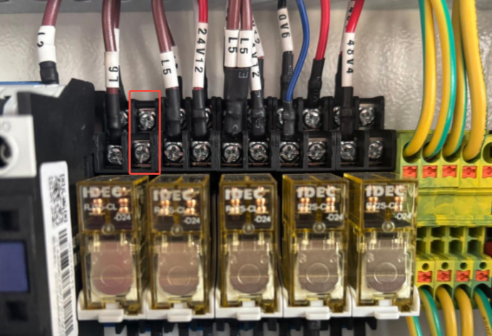 |
| AURURA: | 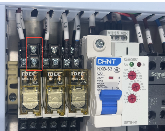 |
2.3 Route the signal cable through the machine panel
Opening the side door and temporarily connecting the cable to the relay can be used as an emergency temporary solution.
For standard long-term installation:
Drill a cable entry hole in the machine's metal panel, install a rubber grommet, and secure the cable to prevent crushing or abrasion.
- Drill a cable hole of appropriate size according to the cable diameter and terminal dimensions.
- Install a rubber grommet to protect the cable from sharp metal edges.
- Route the cable into the machine and secure it according to normal wiring practices (for example, inside the cable duct), ensuring it does not interfere with moving parts.
3. Extending the signal cable (optional)
If the supplied 2-meter cable is too short, you may extend it yourself or contact Thunder to purchase a custom cable with the required length and terminals.
3.1 Purchase Custom Signal Cables
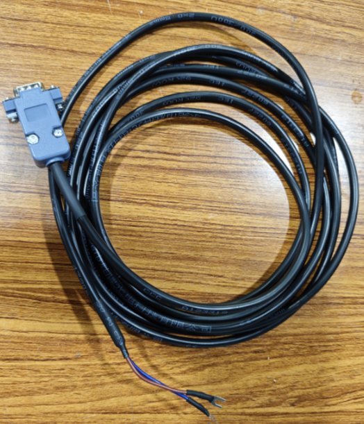
- Custom options may include:
- Specific connection terminals
- Finished cables of specific lengths
- Direct connection between the machine relay and the extractor signal port. Follow Step 1 or Step 2.2 for installation.
3.2 Modify the supplied signal cable (if needed)
Method 1: Direct wire splice (soldering recommended)
| 1. Prepare a 2-core cable (or use two conductors from a multi-core cable). | 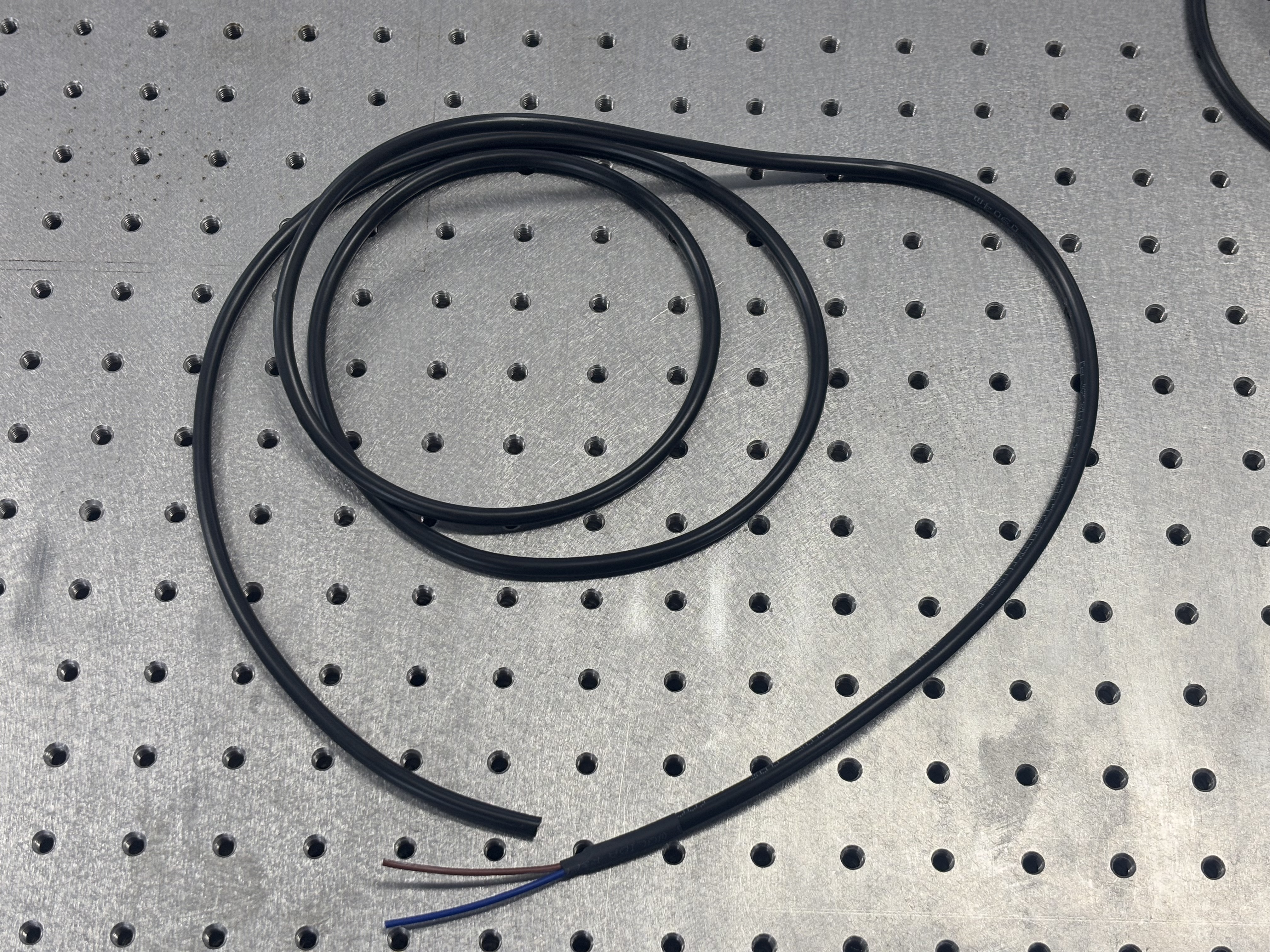 |
| 2. Splice the prepared DB9 wires to the extension cable wires. Soldering is recommended for reliability. | 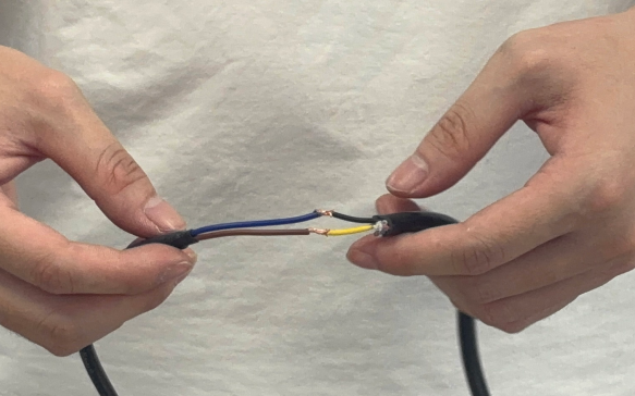 |
| 3. Insulate the joint completely with electrical tape. | 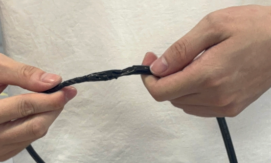 |
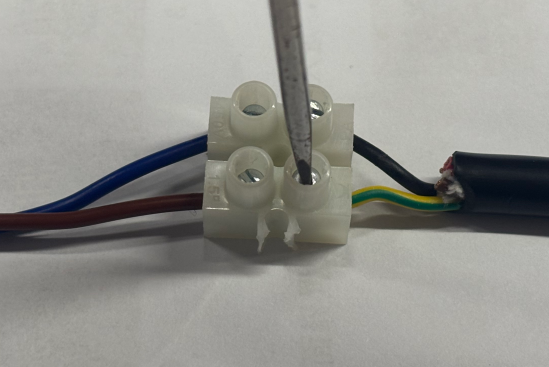
Method 2: Terminal block connection (if available)
| 1. Insert both the DB9 wire and the extension wire fully into the terminal block. | 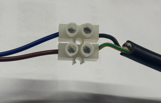 |
|
2. Tighten both sides with a flat-head screwdriver. Note: Wrap any exposed conductors with insulation tape. |
 |
Safety Notes
- All exposed metal connections must be fully insulated to prevent short circuits.
- Route the signal cable away from high-voltage laser cables and power cables to avoid signal interference.
- After installation, perform a full functional test, including laser machine start/stop, extractor linkage operation, and alarm signal transmission.
- During routine maintenance, inspect cable insulation and wear at the cable entry hole regularly.
Still need help?
For specific technical questions or help requests, please open a Ticket with a picture or video, so our Support team can assist you ASAP.
For the information provided in the ticket, please refer to this link: Help Tech Support Troubleshoot Faster
End.
Still stuck?
No bots, no runaround. Talk to a U.S.-based laser tech who knows your machine inside out.