
Thunder AccuMetal Series Unified User’s Manual
THUNDER LASER
SYSTEMS
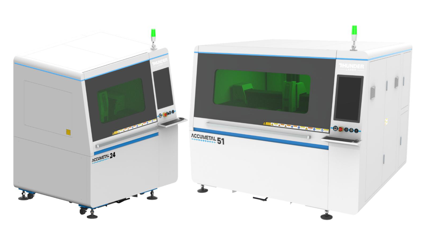
Thunder AccuMetal Series
Unified User’s Manual
For Thunder AccuMetal24, 51
Thunder Laser
www.thunderlaser.com
[email protected]
September 2026
DONGGUAN THUNDERLASER INDUSTRIAL CO., LTD
Dongguan City, Guangdong Province, China
Introduction
Welcome to Thunder Laser products!
This manual serves as the official installation and user guide for Thunder Laser AccuMetal systems. It is divided into six sections: Basic Information & Safety Guidelines, Important Pre-Installation Preparation, Installation Steps, Machine Operation Instructions, Software Operation Instructions, and Maintenance Requirements.
To ensure safe, stable, and efficient operation, all systems must be installed, configured, and operated strictly in accordance with Thunder Laser’s specified requirements. Failure to follow the instructions, conditions, and safety guidelines described in this manual and related documentation may result in system malfunction, reduced performance, shortened service life, increased maintenance costs, or even permanent machine damage. Thunder Laser shall not be held liable for any personal injury, equipment damage, or other losses caused by misunderstanding, improper operation, unauthorized modification, the use of unapproved accessories or components, or any other improper use of the equipment.
Before operating the machine for the first time, please carefully read all materials provided in the knowledge base, including the user manual, safety instructions, installation guides, and related documentation, to ensure a safer and better user experience.
The notes and instructions in this manual outline critical requirements for proper system installation and operation. We strongly recommend that all users fully understand and strictly follow these instructions before installing or operating the equipment. If you encounter any issues during installation or operation, please contact Thunder Laser technical support or customer service for assistance.
Every effort has been made to ensure the accuracy and completeness of this manual. However, technical inaccuracies, omissions, or printing errors may still exist. Thunder Laser continuously improves its products, software, and documentation, and therefore reserves the right to modify or update product specifications, software features, machine design, technical parameters, and the contents of this manual at any time without prior notice.
All images, diagrams, and interface screenshots in this manual are for reference only. The actual product shall prevail. For the latest product information and documentation updates, please refer to the official Thunder Laser website: http://www.thunderlaser.com
Chapter 1. SAFETY
1.1 Definitions
Laser Product
A laser product may be a single laser with or without an independent power supply, or a complex optical, electrical or mechanical system equipped with one or more lasers.
Laser products are generally used for the demonstration of physical and optical phenomena, material processing, data reading and storage, information transmission and display, etc.
Industrial laser cutting/welding equipment, such as CO₂ laser machines, fiber laser cutters and handheld fiber laser welders, all fall into the category of laser products.
Processing Principle
Laser cutting/welding equipment uses high-energy laser beams to perform precise cutting, engraving or welding on materials (such as metals, plastics, wood, etc.).
Laser Classification
Generally speaking, laser products can be divided into the following four categories according to their laser radiation levels:
| Class 1,Class 1M | When used under normal conditions, they do not produce optical radiation harmful to the human body. |
| Class 2,Class 2M | Low-level visible light radiation is safe for the skin, and the eyes can be protected by the natural aversion response to bright light. |
| Class 3R | Class 3R lasers will not cause damage to the naked eye for people who can normally avoid strong light, but they will cause harm to human eyes when observed through lens instruments. |
| Class 3B | May cause eye injury. Class 3B laser products can also cause skin damage when their output level approaches the upper limit of this category. |
| Class 4 | May cause damage to both eyes and skin. Diffuse reflection is also hazardous, and may even ignite irradiated materials. Meanwhile, harmful radiation and fumes are generated through interaction with the target material. |
1. To assess the potential dangers laser systems pose, they are classified into 4 safety classes, Thunder AccuMetal series is a device of class 2. This is guaranteed by the protective housing and the safety installations. When front door is open the machine will stop Class 4 fiber laser for firing and only the Class 2 red laser is accessible. Please note that improper and warranty operation of
the device can override the status of Safety class 2 and can cause the emission of harmful radiation.
2. This laser engraving system contains a Fiber laser of class 4 that emits intensive and invisible laser radiation. Without safety precautions the direct radiation or even diffuse reflected radiation is dangerous!
3. Without safety precautions, the following risks exist with exposure to laser radiation:
Eyes: Burns to the cornea
Skin: Burns
Clothing: Danger of fire
4. Never try to modify or disassemble the laser and do not try to start up a system that had been modified or disassembled!
5. Dangerous radiation exposure can result from the use of operation or adjustment equipment other than that described here, and if different operational methods are performed.
1.2 Hazards
Laser Radiation Hazards
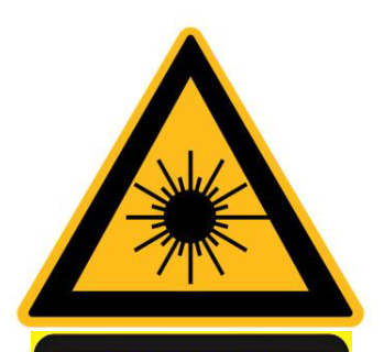
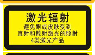
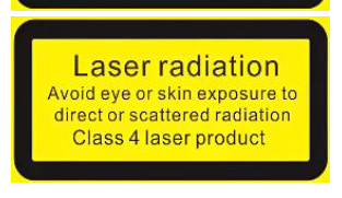
The equipment contains a Class 4 laser. The machine is equipped with an interlock protection system on the front lid, while the side and rear access panels are secured with screws. Under normal operating conditions, users will not be exposed to Class 4 laser radiation. However, exposure may be possible during maintenance or servicing, so appropriate laser safety precautions must still be observed. Direct intrabeam viewing and skin exposure are hazardous, and diffuse reflection also poses risks. Secondary laser beams may be generated at the laser output port and radiate outward at multiple angles. This phenomenon, where the primary laser beam reflects off a flat surface to produce a divergent beam, is known as specular reflection. Although the energy of secondary laser beams is significantly lower than that of the primary laser beam, their intensity can still cause injury to the eyes, skin, or damage to the surface of certain materials.
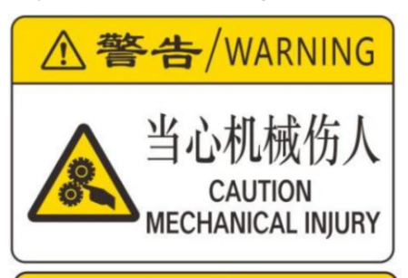
Mechanical Hazards
Mechanical hazards refer to potential injury risks caused by mechanical equipment, tools, or mechanical processes, which may threaten personnel safety, mainly including crushing, impact, entanglement hazards, etc.
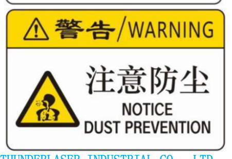
Fume and Dust
Fumes and dust generated during the processing of laser equipment (such as cutting, welding, engraving, etc.) may cause harm to health and the environment. The fumes may contain metal particles (such as lead, chromium, nickel), plastic volatiles, or ceramic dust, and some fumes are corrosive or allergenic.
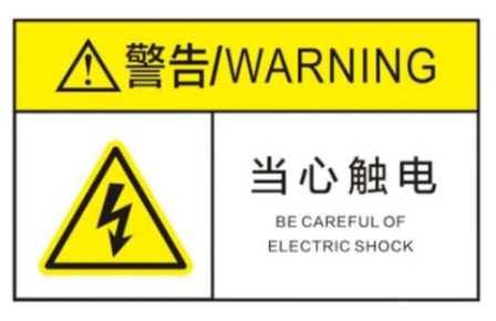
Electric Shock
Laser equipment typically operates at working voltages of AC 220V or AC 380V. Line aging, humid environments, or poor insulation may lead to short circuits or electric leakage. Ground faults (such as incorrect grounding connection) may increase the risk of electric shock.
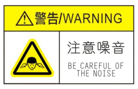
Noise
Laser equipment may generate noise during operation. The airflow at the laser head during processing (such as air/nitrogen/oxygen assist gas injection) produces noise; the cooling systems (fans, water pumps) or high-frequency power supplies of some lasers may also generate noise, as do other auxiliary equipment (such as air compressors, exhaust systems).
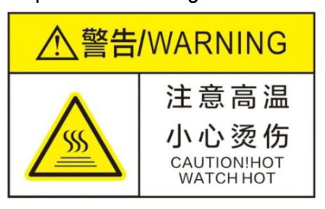
High Temperature
Laser equipment generates high temperatures during operation, mainly from the laser itself, the thermal effect of processed materials, and auxiliary equipment. During laser cutting/welding, the vaporization/melting of metals or plastics produces high-temperature slag and spatter (up to thousands of degrees Celsius). The processed high-temperature workpiece or worktable surface dissipates heat continuously, and auxiliary equipment such as air compressors may generate high temperatures after long-term operation.
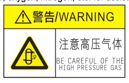
High-Pressure Gas
Laser equipment usually uses high-pressure gases during operation, such as air, oxygen, nitrogen, etc. for assist cutting. If the gas cylinder bursts or the pipeline ruptures, it may cause fragment projection. Leakage of inert gases (such as nitrogen, argon) may reduce the oxygen concentration in the environment (<19.5% is a hypoxia hazard), while oxygen leakage may cause spontaneous combustion of grease or metal dust under oxygen-assisted combustion.
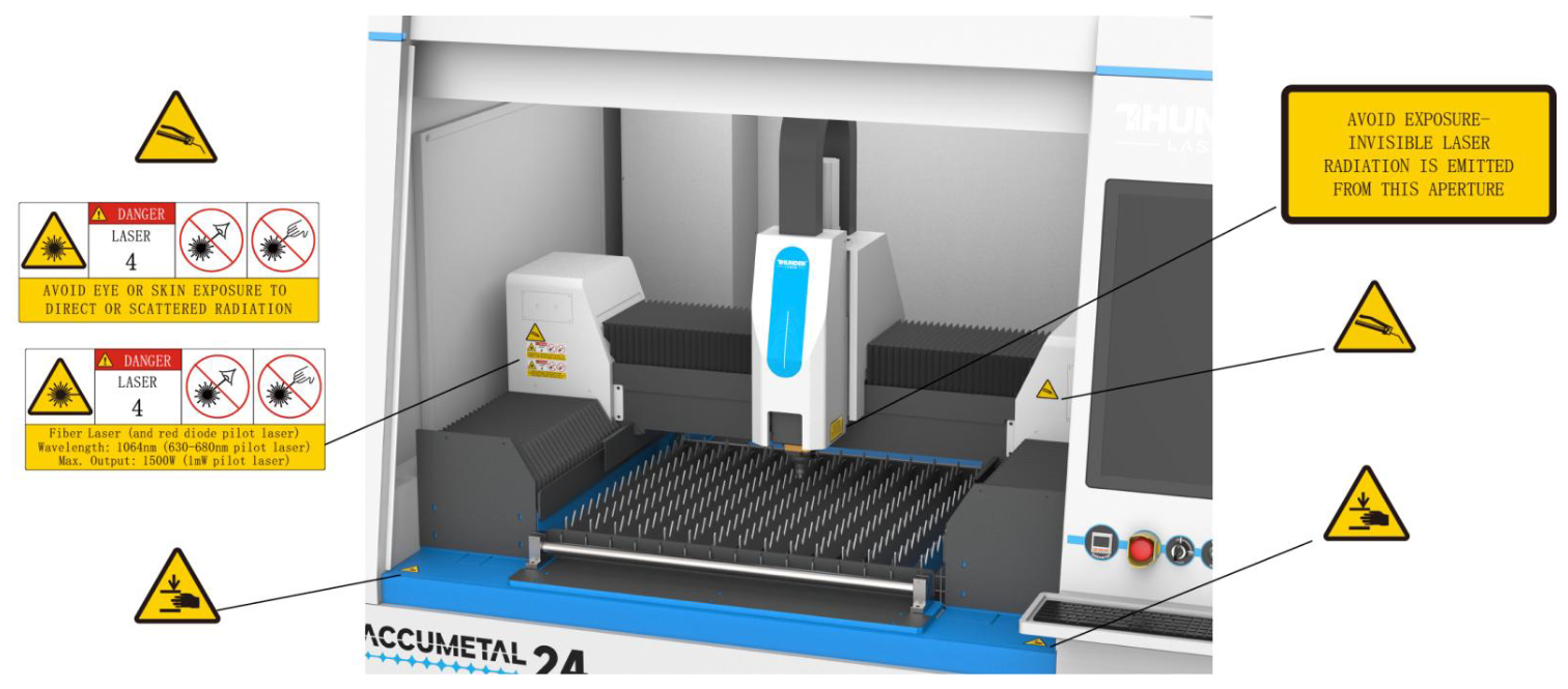
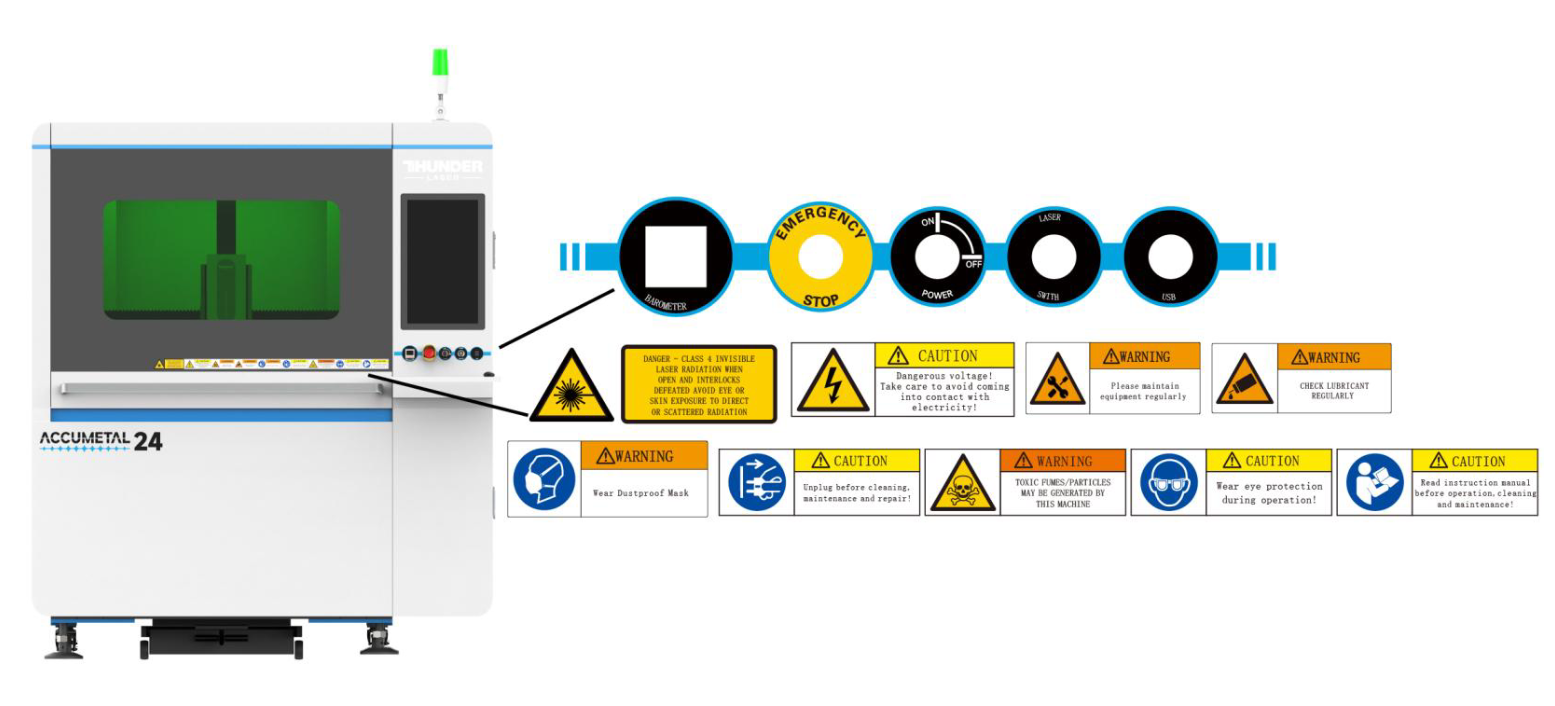
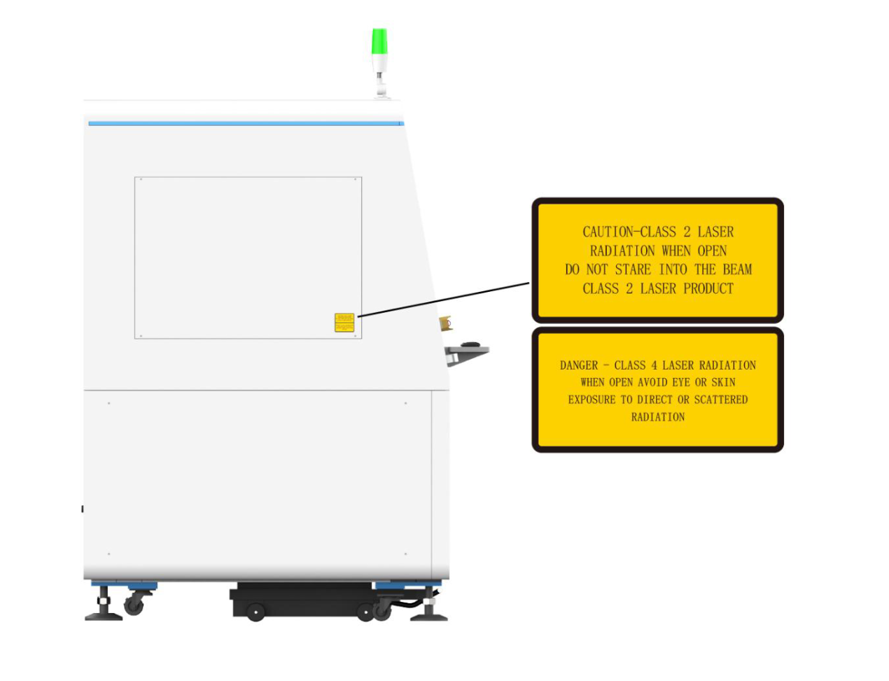
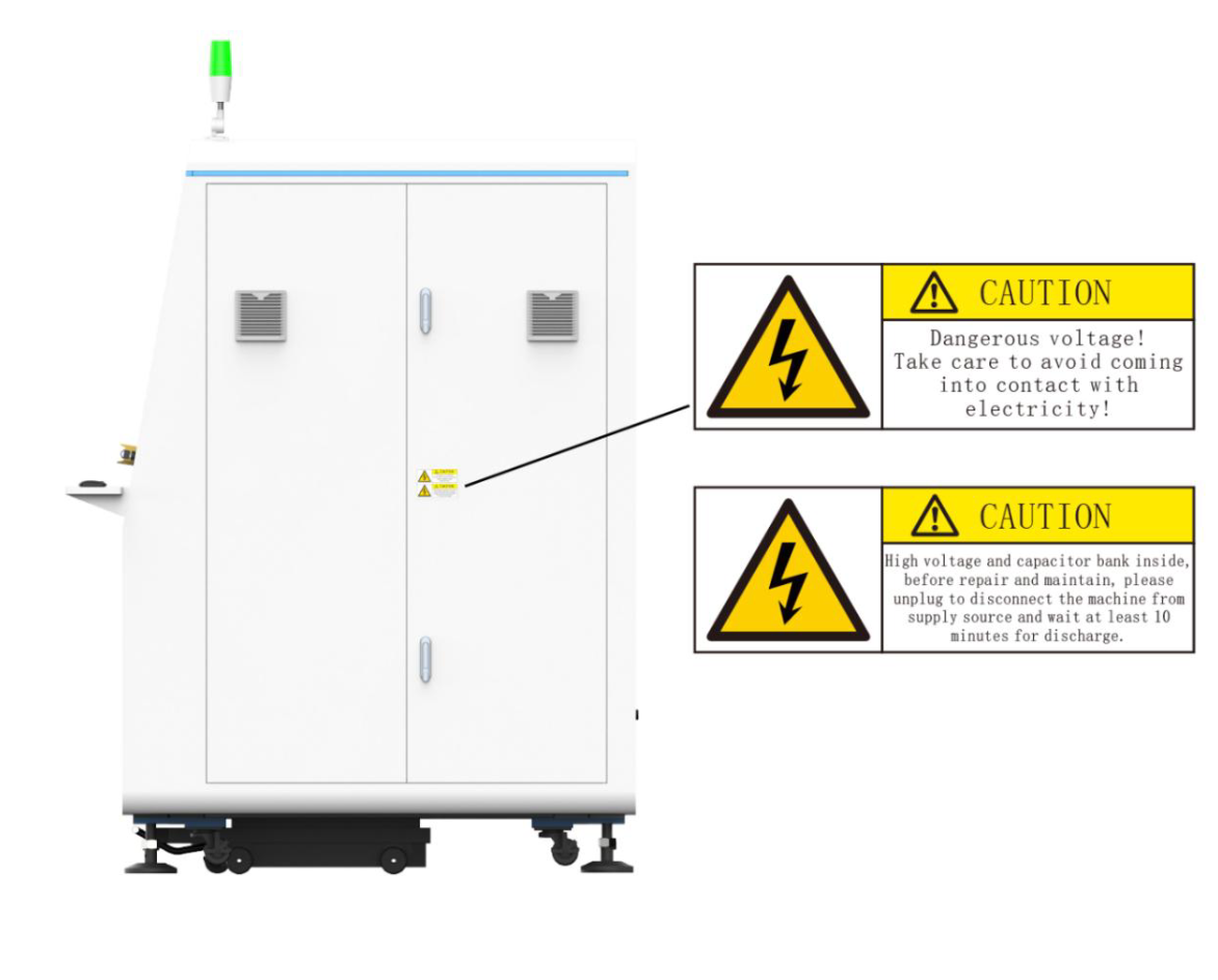
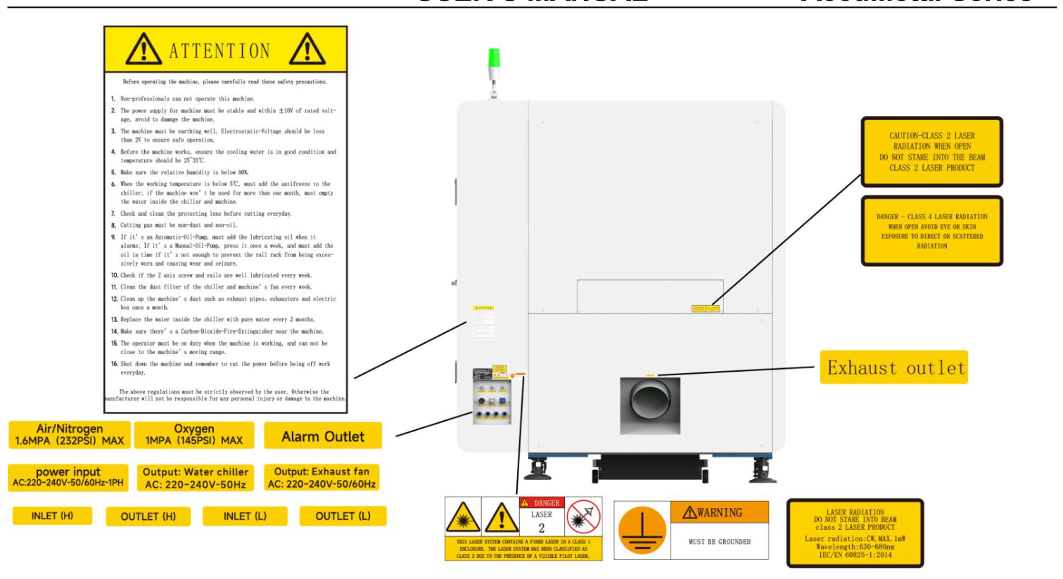
1.3 Warning and Information Labels

The warning and information labels in various locations if the machine should always be read carefully and understood. If labels are lost or damaged, they must be replaced immediately.
1.4 Protection
Personal Protection
Personal protection mainly relies on personal protective equipment worn by individuals. In terms of laser safety, it mainly refers to the use of laser protective goggles, but also includes special protective work clothes for skin protection (such as gloves, face masks, protective clothing, etc.), respiratory protection equipment for protecting against dust and fumes, and earplugs/earmuffs for protecting against excessive noise.

Protective Goggles
- Laser protective goggles shall have obvious marks, and the correct protective goggles suitable for specific lasers shall be selected;
- Comfortable to wear, providing the widest possible field of vision;
- It shall have a certain degree of airtightness and good air permeability to avoid fogging;
- Have appropriate visible light transmittance;
- Avoid using flat reflective lenses that can produce harmful specular reflection;
- The frame and side parts shall have a certain protective capacity.
Introduction to Common Types of Laser Protective Goggles/Protective Face Masks
| Laser Type | Recommended Specifications for Protective Goggles/Face Masks |
|---|---|
| CO₂Laser | Wavelength 10.6 μm, OD≥4, Transmittance >70% (Colorless) |
| Fiber Laser | Wavelength 1064 nm, OD 5~6 (Amber or Green Lenses) |
| UV Laser | Wavelength 200~400 nm, OD 4+ (Dark Lenses) |
Protective Clothing
In addition to protective gear such as goggles, face shields and gloves, it is recommended to wear protective clothing if conditions permit.
- Protective clothing should be made of suitable fire-resistant and heat-resistant materials;
- Long-sleeved protective clothing is recommended, and skin exposure should be avoided as much as possible.
Introduction to Common Types of Protective Clothing
| Laser Type | Recommended Specifications for Protective Clothing |
|---|---|
| CO₂Laser | Wavelength 10.6 μm, Aluminum-plated flame-retardant clothing (infrared reflective) |
| Fiber Laser | Wavelength 1064 nm, Aramid material (protection against molten metal spatter) |
| UV Laser | Wavelength 355 nm, UV penetration-proof sealed protective clothing |
Fume and Noise Protective Equipment
Fume protection: Wear an N95/KN95 mask. Depending on the fume conditions in the actual working environment, wear a gas mask if necessary.
Noise protection: Wear hearing protection when the noise in the working environment exceeds 85dB. Select earplugs/earmuffs with an SNR (Noise Reduction Rating) ≥ 25dB.

1.5 Safety Management
Safety Training
The enterprise shall provide relevant training for personnel operating laser equipment, mainly including the following contents:
- Be familiar with the working process of laser equipment.
- Safety operation procedures for laser equipment.
- Understand the potential hazards of laser equipment.
- Proper use of personal protective equipment.
- Be familiar with relevant warning and safety signs.
Procedure Improvement
Enterprise management shall inspect whether the current enterprise systems and processes need to be supplemented and improved, mainly including the following contents:
- Supervision over the implementation of personal protective equipment.
- Establish a complete accident reporting procedure.
- Supervision of workshop electrical circuits and fire protection facilities.
- Appointment of a Laser Safety Officer.
Enterprises with conditions may appoint a Laser Safety Officer. The Laser Safety Officer shall be familiar with the assessment and control methods of laser hazards, be responsible for safety protection in the production workshop, promote knowledge on laser safety protection, and inspect laser protection conditions. If any non-compliance with safety requirements is found, the officer has the right to stop the use of the laser equipment and allow its use only after measures have been taken to meet the safety protection requirements. In the event of a laser injury accident, the officer shall report it in a timely manner and record it in the technical safety file.
Safe Operation Procedures for Laser Equipment
Safe Operation Procedures for Laser Cutting/Welding Equipment
- Laser cutting/welding equipment shall comply with the safe operation procedures for general cutting/welding equipment.
- Operators must receive training from the company and master relevant knowledge of the equipment operation system.
- Operators must wear personal protective equipment as required, such as protective goggles.
- Keep the laser, machine body and surrounding area clean and tidy on a daily basis.
- Regularly inspect the workshop electrical circuits and fire protection facilities to eliminate potential safety hazards in a timely manner.
- In accordance with fire safety requirements, place carbon dioxide fire extinguishers in a fixed and easily accessible location near the laser equipment.
- When using air compressors, please comply with the national standard GB/T 10892-2021 Safety Rules and Operation Procedures for Stationary Air Compressors.
- When using gas cylinders/tanks, avoid crushing equipment circuits or pipelines. The use and transportation of gas cylinders/tanks shall comply with relevant supervision regulations. Do not expose gas cylinders/tanks to direct sunlight or near heat sources.
- Do not place paper, cloth, alcohol or other flammable and explosive materials near unprotected laser beams.
- Ensure good ventilation in the equipment working area and that a smoke exhaust system is provided.
- Before starting the machine, check for obstacles on the machine table and ensure the material height is lower than the laser head to avoid collision.
- Do not open any installed equipment covers while the equipment is energized.
- During equipment operation, it is strictly prohibited to place any part of the body within the laser path range.
- During equipment operation, it is strictly prohibited to place any part of the body within the equipment travel range.
- The equipment must not operate unattended. The operator shall not leave the post without permission or entrust others to take care of it. If it is necessary to leave, stop the machine or cut off the power switch and close the gas valves.
- Do not process a material if you are unsure whether it can be processed by laser, so as to avoid potential hazards from fumes and vapors.
- Do not modify equipment parameters without permission to avoid affecting normal operation. Turn off the laser or the shutter when the equipment is not in use.
- After inputting the program for a new workpiece, run a test first and check its operation. Formal processing shall only be carried out after confirming that the processing results meet relevant requirements.
- If any abnormality is found during equipment operation, stop the machine immediately. Processing may resume only after troubleshooting in a timely manner.
- Do not stand on the machine table while the equipment is energized. If it is necessary to enter the machine table, be sure to shut down and cut off power to the equipment first.
Requirements for Waste Gas Treatment of Laser Equipment
Laser Equipment Exhaust Gas Treatment Guide
○Sources and Hazards of Waste Gas
Waste gases generated during laser cutting and engraving may include:
| Processing Type | Exhaust Gas Type |
|---|---|
| Metal Processing | Metal oxide dust (e.g., aluminum, titanium, stainless steel dust) |
| Non-metal Processing | Plastics / Acrylic: release benzene series (e.g., benzene, toluene), hydrogen cyanide (HCN), formaldehyde, etc.Wood / Composite materials: produce tar, particulate matter (PM2.5 / PM10)Coated materials: may release heavy metal vapors (e.g., chromium, nickel) |
Hazards: Long-term inhalation may lead to respiratory diseases and cancer risks. Some gases (such as HCN) are highly toxic.
○Exhaust Gas Treatment Standards
Exhaust Gas Treatment StandardsCompliance with national and regional regulations is required, such as:
China: Integrated Emission Standard of Air Pollutants (GB 16297-1996)
EU: EN 14975 (Indoor Air Quality)
US: OSHA PEL (Permissible Exposure Limits)Key Limit Values (Examples):
| Pollutant | Allowable Concentration(mg/m³) |
|---|---|
| Particulate Matter(PM10) | ≤10 |
| Formaldehyde | ≤0.5 |
| Benzene | ≤1 |
○Exhaust Gas Treatment Solutions
1 Ventilation System Requirements
Local Exhaust: The distance between the air inlet and the processing area shall be ≤ 30cm, and the wind speed shall be ≥ 0.5m/s.Pipelines shall be designed with anti-static properties (to avoid dust explosions).Overall Ventilation: The workshop ventilation rate shall be ≥ 10 times per hour (≥ 20 times per hour for toxic materials).
2 Selection of Purification Equipment
| Exhaust Gas Type | Recommended Purification Equipment | Purification Principle |
|---|---|---|
| Particulates (Dust) | Baghouse Dust Collector / Electrostatic Precipitator | Filtration / Electrostatic Adsorption |
| Volatile Organic Compounds (VOCs) | Activated Carbon Adsorption Device / Catalytic Combustion Equipment | Adsorption / High-Temperature Oxidative Decomposition |
| Acidic Gases (e.g., HCN) | Alkaline Spray Tower | Acid-Base Neutralization Reaction |
Combined Solution Example: Air Collection Hood → Cyclone Dust Removal → Activated Carbon Adsorption → High-Altitude Emission (≥15m)
3 Equipment Maintenance Requirements (Example)
Daily Inspection: Ensure exhaust ducts are free of blockages and fans operate normally.
Regular Replacement: Replace activated carbon every 3–6 months (depending on usage frequency).
Replace dust filter bags when pressure difference exceeds 1500Pa.
○Operating Specifications
- Pre-treatment: Confirm material composition before processing to avoid processing unknown or prohibited materials.
- During Operation: Purification equipment shall be started before the laser equipment and shut down later to ensure complete exhaust extraction.
- Emergency Measures: If exhaust gas leakage is detected, stop the machine immediately and evacuate personnel.
○Monitoring and Recording
- Sensor Installation: Monitor PM2.5 and VOCs concentrations in real time.
- Regular Testing: Entrust a third-party organization to conduct exhaust emission testing annually.
- Record Keeping: Maintenance logs and inspection reports shall be retained for at least 3 years.
○Prohibited Behaviors
- Direct exhaust emission without purification equipment.
- Processing highly toxic materials (such as PVC) in enclosed spaces.
Appendix: Exhaust Gas Treatment Recommendations for Common Materials
| Material | Main Pollutants | Treatment Method |
|---|---|---|
| Stainless Steel | Chromium/nickel oxides | Dust removal + activated carbon adsorption |
| Acrylic | Formaldehyde, methacrylates | Activated carbon + catalytic combustion |
| PVC | Hydrogen chloride(HCl) | Alkaline liquid spray + HEPA filtration |
Emergency Handling of Equipment Safety Accidents
Emergency Handling Guide for Laser Equipment Safety Accidents
○Accident Type Identification
①Laser Radiation Injury: Accidental exposure of personnel to laser beams due to misoperation (skin/eye burns).
②Fire Accident: Laser ignites processing materials or surrounding combustibles.
③Electrical Accident: Short circuit, overload, etc., in equipment or external circuits.
④ Gas Leakage: Leakage in the laser exhaust gas treatment system (such as ozone, toxic VOCs).
○Emergency Handling Procedures
① Laser Radiation Injury
Immediate Action: Press the emergency stop switch of the equipment and turn off the power of the laser equipment; remove the injured person and check the injured area (skin erythema/eye pain, blurred vision).
Medical TreatmentSkin Burns: Rinse with cold water for 15 minutes, cover with sterile dressings, and send to the hospital.
Eye Exposure: Do not rub the eyes, rinse with normal saline, and immediately send to the ophthalmology department (indicate laser wavelength and power).
② Fire AccidentInitial Fire
Fighting: Use a CO₂ fire extinguisher (do not use water or dry powder fire extinguishers, which may damage optical components); cut off the equipment power and gas source.
Fire Expansion: Activate the fire alarm, evacuate personnel, and close fire doors; if chemical combustion is involved, wear a gas mask.
Post-Accident Handling: Investigate the cause of the fire (such as excessive dust, damaged lines, etc.).
③ Electrical Accident
Cut Off The Power Supply: Cut off the main power supply, use insulating tools to remove faulty components; professional personnel check whether the equipment circuit or external circuit is normal.Personnel
Electric Shock: Use an insulating object to remove the power supply and immediately perform cardiopulmonary resuscitation (CPR).
④ Gas Leakage
Immediate Action: Turn off the exhaust gas treatment system and start emergency ventilation; evacuate personnel to the upwind direction to avoid inhalation (ozone, acid mist, etc., can cause suffocation).
Leak Source Control: Wear a gas mask and gloves to check for pipeline damage or valve failure; repair after confirming safety with a gas detector.
Poisoning First Aid: Move the poisoned person to a ventilated place, provide oxygen (if available), and call the emergency number.
Chapter 2. PRE-INSTALLATION PREPARATION & REQUIREMENTS
2.1 Technical Specifications
| THUNDER LASER-HIGH SPEED PRECISION SERIES FIBER CUTTER TECHNICAL PARAMETERS | |||||
|---|---|---|---|---|---|
| TYPE | MODEL | DIMENSION/LENGTH*WIDTH*HEIGHT | WEIGHT/KG | CUTTING RANGE | Packing Dimensions and Packed Weight |
| HIGH SPEEDPRECISIONSERIESFIBERCUTTER | Thunder AccuMetal24 | 1750 x 1590 x 2260mm | 1300KG | 610×610mm | 1850 x 1690 x 2300mm,1420kg |
| Thunder AccuMetal51 | 2130 x 2450 x 2015mm | 2000KG | 1300 x 1300mm | 2230 x 2550 x 2100mm,2200kg | |
2.2 Pre-Installation Requirements
| THUNDER LASER-PREPARATIONS AND REQUIREMENTS BEFORE INSTALLATION FOR HIGH SPEED PRECISION SERIES FIBER CUTTER | |||
|---|---|---|---|
| LASER POWER | 1500W | 3000W | |
| ELECTRICITY REQUIREMENTS | ELECTRICITY DEMAND | 3 PHASE ALTERNATING CURRENT(NEEDED NEUTRAL-WIRE)AC380V±10V,50Hz/60Hz,STABILIZER IS RECOMMENDED MUST BE GROUNDED EFFECTIVE,ENSURE THE GROUNDING RESISTANCE ≤4Ω | |
| RATED POWER | 10KW | 15KW | |
| EXTERNAL LEAKAGE SWITCH SPECIFICATION REQUIR | Single-phase 220V: ≥50AThree-phase 380V: ≥32A | Three-phase 380V: ≥32A | |
| Note: For more details please check Chapter 3.6 Electrical Power Connection | |||
| GAS REQUIREMENTS | OXYGEN REQUIREMENT | 0.2MPa < OXYGEN INPUT PRESSURE < 1MPa,PURITY≥99.99% | |
| NITROGEN REQUIREMENT | 0.6MPa < NITROGEN INPUT PRESSURE < 1.6MPa(User may adjust according to needs),PURITY≥99.99% | ||
| AIR REQUIREMENT | 0.6MPa < AIR INPUT PRESSURE < 1.6MPa(User may adjust according to needs), MUST BE DRY,NO WATER AND NO OIL | ||
| GAS FLOW REQUIREMENT | GAS FLOW>1.0m³/min | ||
| WATER REQUIREMENTS | CHILLING WATER | DISTILED WATER,PURIFIED WATER OR DEIONIZED WATER NOTE:ANTIREZE SHOULD BE ADDED IN LOW-TEMPERATURE ICING AREAS,CLARIANT ANTIFREEZE IS RECOMMENDED | |
| CAPACITY | AROUND 16L | AROUND 22L | |
| ENVIRONMENT REQUIREMENTS | PLANT FOUNDATION | FOUNDATION STANDARD: 500KG/m², AMPLITUDE ≤ 50μm,AMPLITUDE ACCELERATION ≤ 0.05GREQUIRING NO LARGE STAMPING VIBRATION EQUIPMENT | |
| NEARBY THERE SHOULD BE NO STRONG ELECTROMAGNETIC SIGNAL INTERFERENCE NEAR THE INSTALLATION EQUIPMENT AND THERE SHOULD BE NO RADIO TRANSMISSION OR RELAY STATIONS AROUND THE INSTALLATION AREA | |||
| ENVIRONMENT TEMPERATURE | 5-40℃ | ||
| ENVIRONMENT HUMIDITY | ≤80% | ||
| ENVIRONMENT CLEANLINESS | THE EQUIPMENT SPACE MUST ENSURE NO SMOKE AND DUST,AVOID WORKING ENVIRONMENTS WITH SEVERE DUST SUCH AS METAL POLISHING AND GRINDING, AND INSTALL ANTI-STATIC FLOORING AND CONNECT SHIELDING WIRES | ||
| OTHERS REQUIREMENTS | DISCHARGE TOOL | FORKLIFT,CRANE OR AERIAL CRANED (advice≥3.0T) | |
| LENS CLEANING TOOLS | ALCOHOL(ANHYDROUS ETHANOL) CONCENTRATION >99.9%,DUST-FREE COTTON SWAB (NON-WOVEN FABRIC) | ||
| MATERLALS | ALL THE MATERIAL TYPES TO BE PROCESSED | ||
| OPERATOR | FAMILIAR WITH COMPUTER ROUTINE OPERATION,READING AND MODIFYING GRAPHICS | ||
Chapter 3. PROCESS OF INSTALLING
3.1 Unpacking
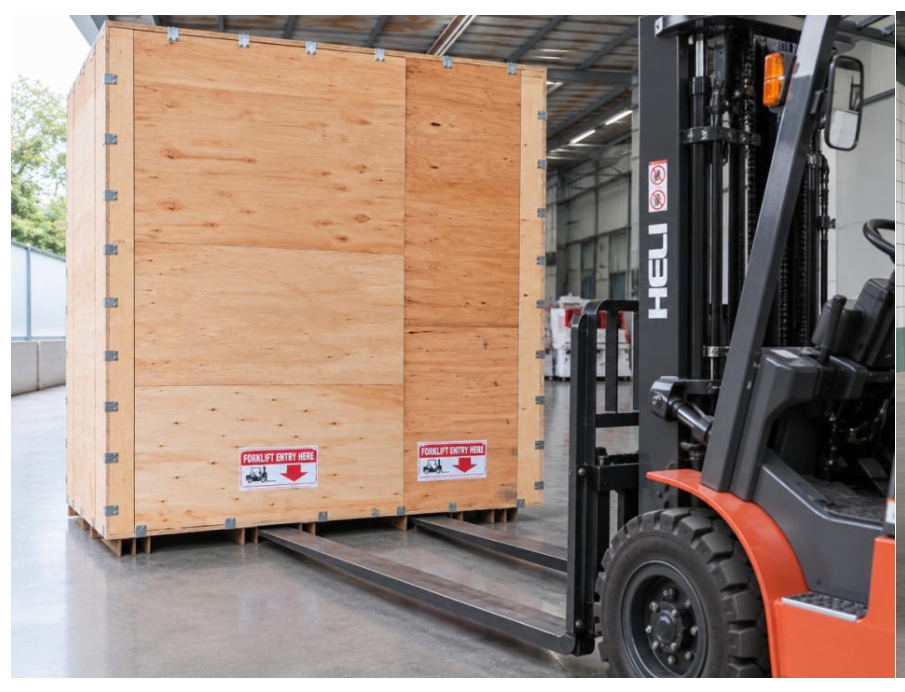
Your Thunder AccuMetal machine is shipped in a wooden crate and includes the metal cutting machine and a separated crate with related accessories. The following steps will guide you through the unpacking and assembly process. Please follow them carefully.
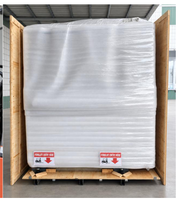
- Place the wooden crate in a spacious, level area before unpacking.
- Open the crate and carefully remove all protective foam, wrapping plastic film, securing blocks, and other packaging materials.
- Unbox the accessory box containing the parts required for installation and verify its contents.
- Use a forklift of sufficient capacity to lift the machine from the pallet. Insert the forks only at the designated lifting points indicated by the forklift entry labels.
- The machine is equipped with four casters. After removing the machine from the pallet, use the casters to move it to the installation location. Move the machine slowly and only across a smooth, level floor.
- If a pallet jack is used to move the machine, check the fork width, spacing, and insertion position before lifting. Make sure the forks do not contact the scrap collection hopper underneath the machine, as this may deform or damage the hopper.
- If there is insufficient clearance for the pallet jack, when necessary, remove the scrap collection hopper before inserting the pallet jack in the direction indicated by the forklift entry labels, this requires removing the lower access panels at the front, rear, and left side of the machine by loosening their screws..
- After positioning and leveling the machine according to the instructions below, reinstall the scrap collection hopper and all access panels.
3.2 Location
Before installing the machine, please choose a suitable installation location. Follow the guidelines below:
The operating environment requirements for the equipment are detailed in Table. Users must prepare the installation site accordingly prior to installation.
| ENVIRONMENT REQUIREMENTS | PLANT FOUNDATION | FOUNDATION STANDARD: 500KG/m², AMPLITUDE ≤ 50μm, AMPLITUDE ACCELERATION ≤ 0.05GREQUIRING NO LARGE STAMPING VIBRATION EQUIPMENT NEARBY.THERE SHOULD BE NO STRONG ELECTROMAGNETIC SIGNAL INTERFERENCE NEAR THE INSTALLATION EQUIPMENT.AND THERE SHOULD BE NO RADIO TRANSMISSION OR RELAY STATIONS AROUND THE INSTALLATION AREA. |
| ENVIRONMENT TEMPERATURE | 5-40℃ | |
| ENVIRONMENT HUMIDITY | ≤80% | |
| ENVIRONMENT CLEANLINESS | THE EQUIPMENT SPACE MUST ENSURE NO SMOKE AND DUST, AVOID WORKING ENVIRONMENTS WITH SEVERE DUST.SUCH AS METAL POLISHING AND GRINDING, AND INSTALL ANTI-STATIC FLOORING AND CONNECT SHIELDING WIRES. |
Clearance Guidelines:
- When operated as a standalone unit, it is recommended to leave a minimum clearance of 1.2 meters around the entire perimeter of the machine, as shown in Figure.
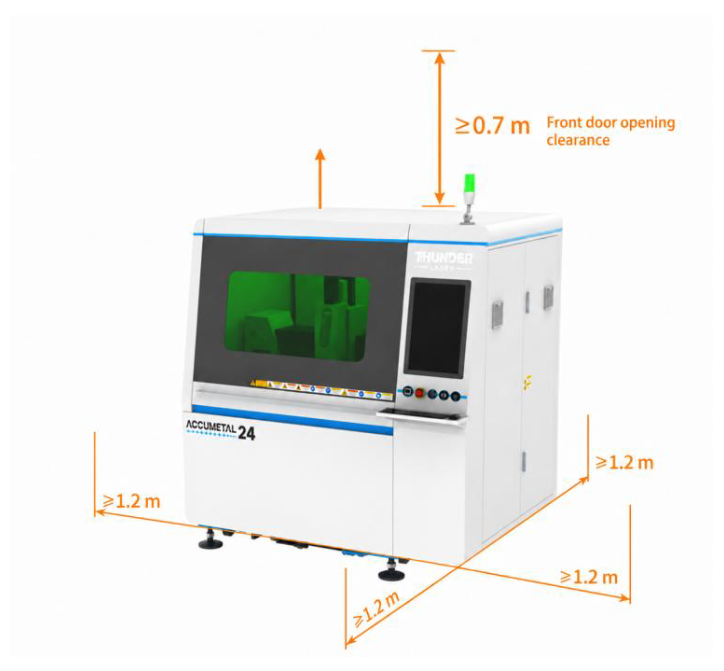
- When operated alongside auxiliary equipment, maintain a minimum clearance of 1.2 meters on the left and right sides. The front and rear clearances can be adjusted based on actual operational needs.
3.3 Before Installation
- Remove the packaging from all external accessories shipped with the machine, then locate the toolbox as shown below.
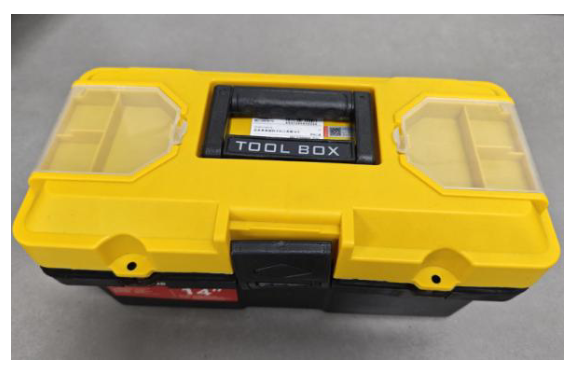
The toolbox contains a set of machine keys, a USB drive, maintenance tools, and other accessories.
Note: The USB drive may contain software, manuals, library files, and other useful resources.
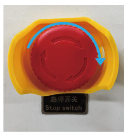
- Reset the Emergency Stop button by turning it in the direction of the arrow. Familiarize yourself with the location and operation of the Emergency Stop button.
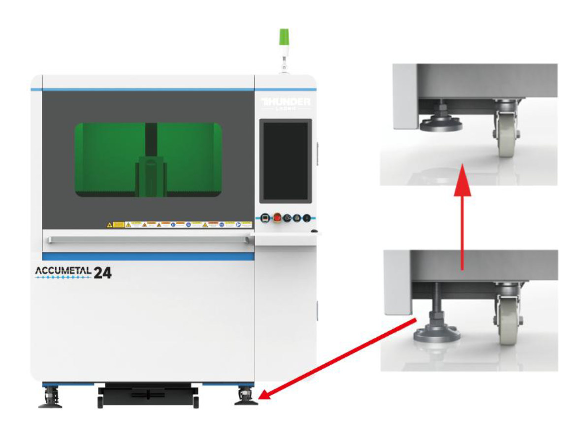
- Once the machine has been moved to its final installation location, make sure to re-secure the four leveling feet at each corner. See the illustration below.
3.4 Leveling the Machine
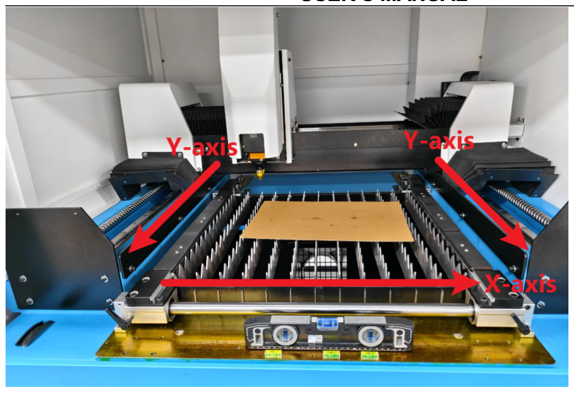
- Leveling Reference: XY-axis guide rail
- Tools Required: Spirit level, or laser level meter(if available)
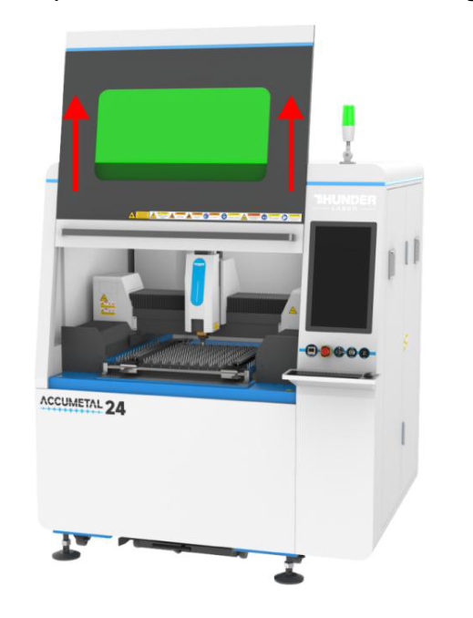
- Open the door, as shown in below figure.
- The X-axis guide rail is located inside the dust cover of the X-axis gantry. Place the spirit level on the specified reference surface of the work table and X/Y-axis guide rail.
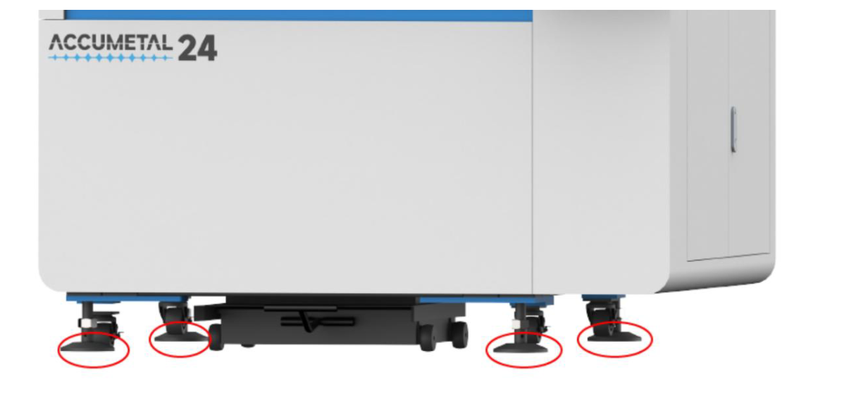
- Lower and adjust the four leveling feet at the bottom of the machine until the machine is fully supported by the leveling feet.
- Adjust the leveling feet gradually and alternately while checking the spirit level. Confirm the machine is level and stable in both the left-to-right and front-to-rear directions.
- If a leveling foot cannot be adjusted easily, use a suitable jack or pallet jack to raise the machine slightly. Position the lifting point directly beneath a structural crossbeam at the bottom of the machine.
3.3 Chiller Installation
- Fill the water chiller with distilled or deionized water through the water injection port. Continue adding water until the indicator reaches the high-level mark in the yellow zone, as shown in Figure.
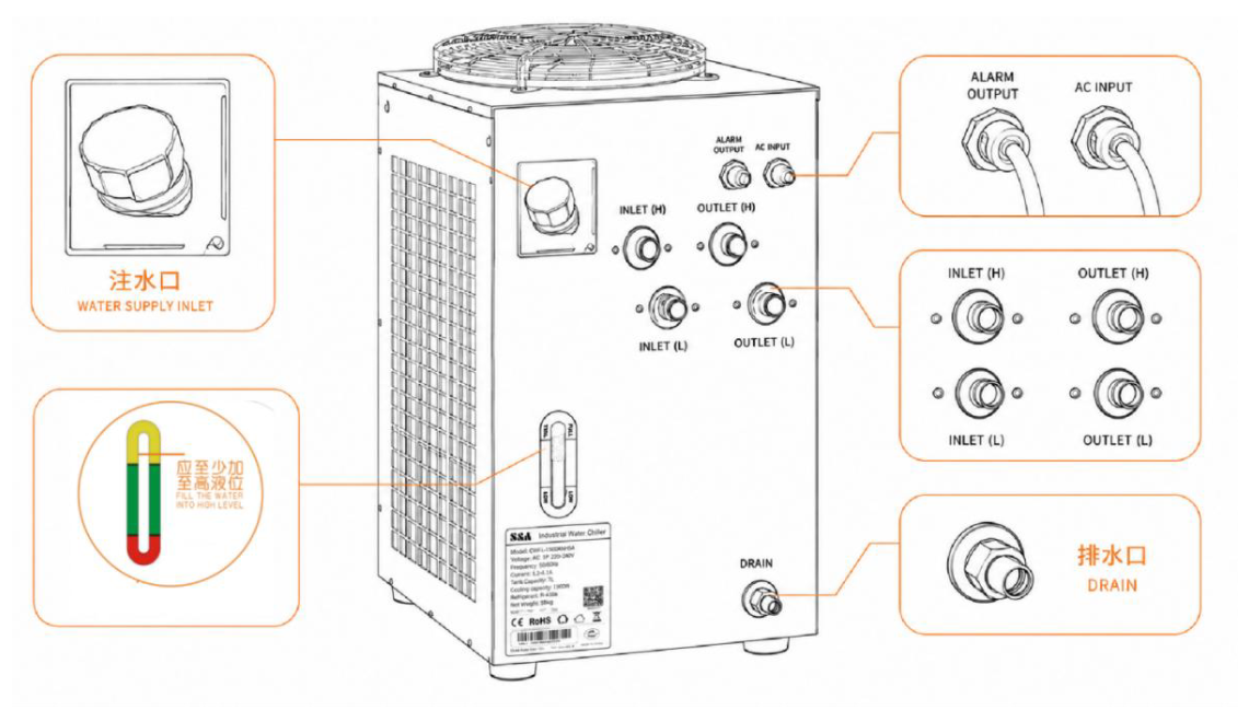
- Connect the provided water hoses between the chiller and the machine.
- Connect Chiller INLET L to Machine INLET L (and OUTLET L to OUTLET L).
- Connect Chiller INLET H to Machine INLET H (and OUTLET H to OUTLET H).
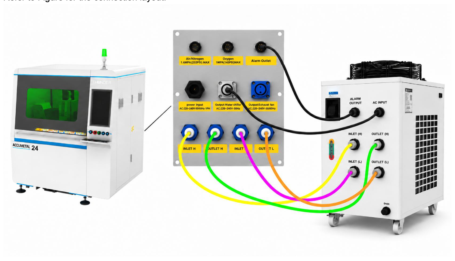
3.4 Exhaust Installation
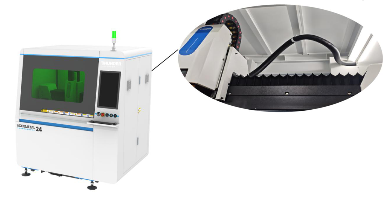
- Install the exhaust pipe support bracket onto the top of the machine, as shown in Figure.
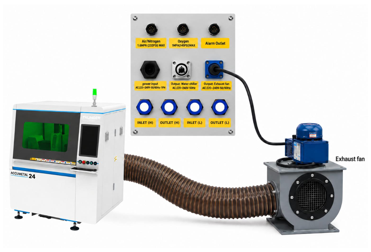
- Connect the exhaust hose from the machine's rear exhaust outlet to the fan's inlet. Then, securely connect the fan’s outlet exhaust hose (routing it outdoors or to a filtration system), as shown in Figure.
3.5 Gas Installation
The machine typically uses compressed air or Nitrogen (N₂) as the cutting assist gas, as detailed in Table and Figure.
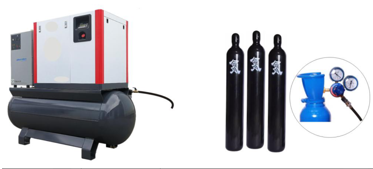
| GAS REQUIREMENTS | NITROGEN REQUIREMENT | NITROGEN INPUT PRESSURE<1.6MPa(User may adjust according to needs), PURITY≥99.99% |
| AIR REQUIREMENT | AIR INPUT PRESSURE<1.6MPa(User may adjust according to needs), MUST BE DRY, NO WATER AND NO OIL | |
| GAS FLOW REQUIREMENT | GAS FLOW>1.0m³/Min |
- Using Compressed Air: When using compressed air, ensure it is perfectly dry and pure. Refer to Figure for hose connection instructions.
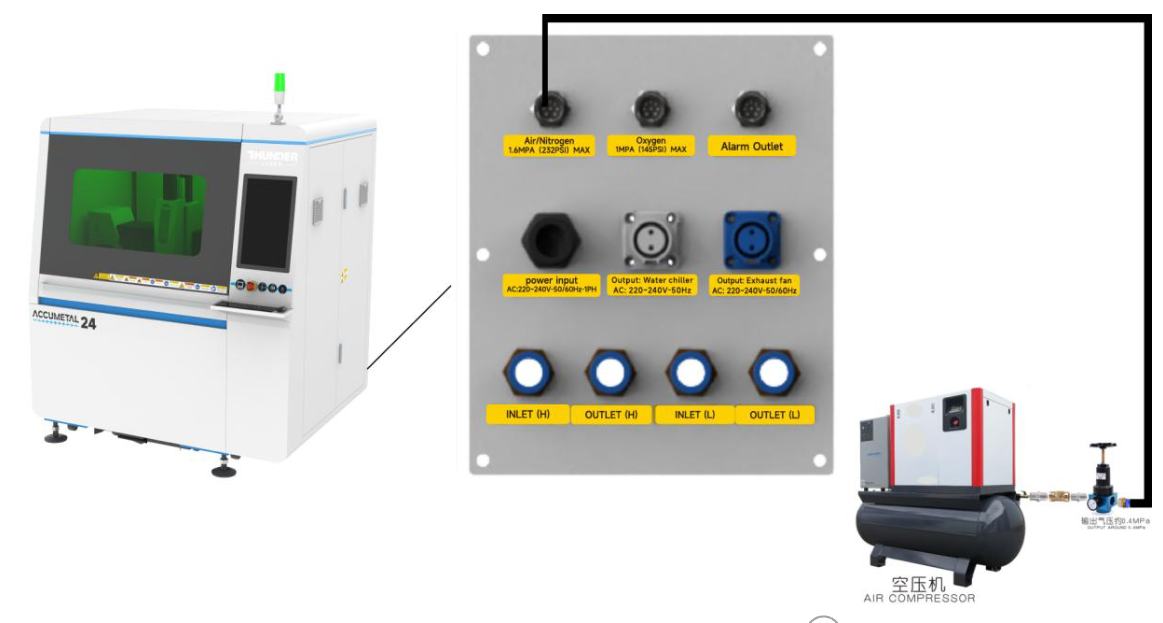
- Using Nitrogen: When using bottled or liquid Nitrogen, install a pressure reducing valve and connect the output gas hose to the machine, as shown in Figure.
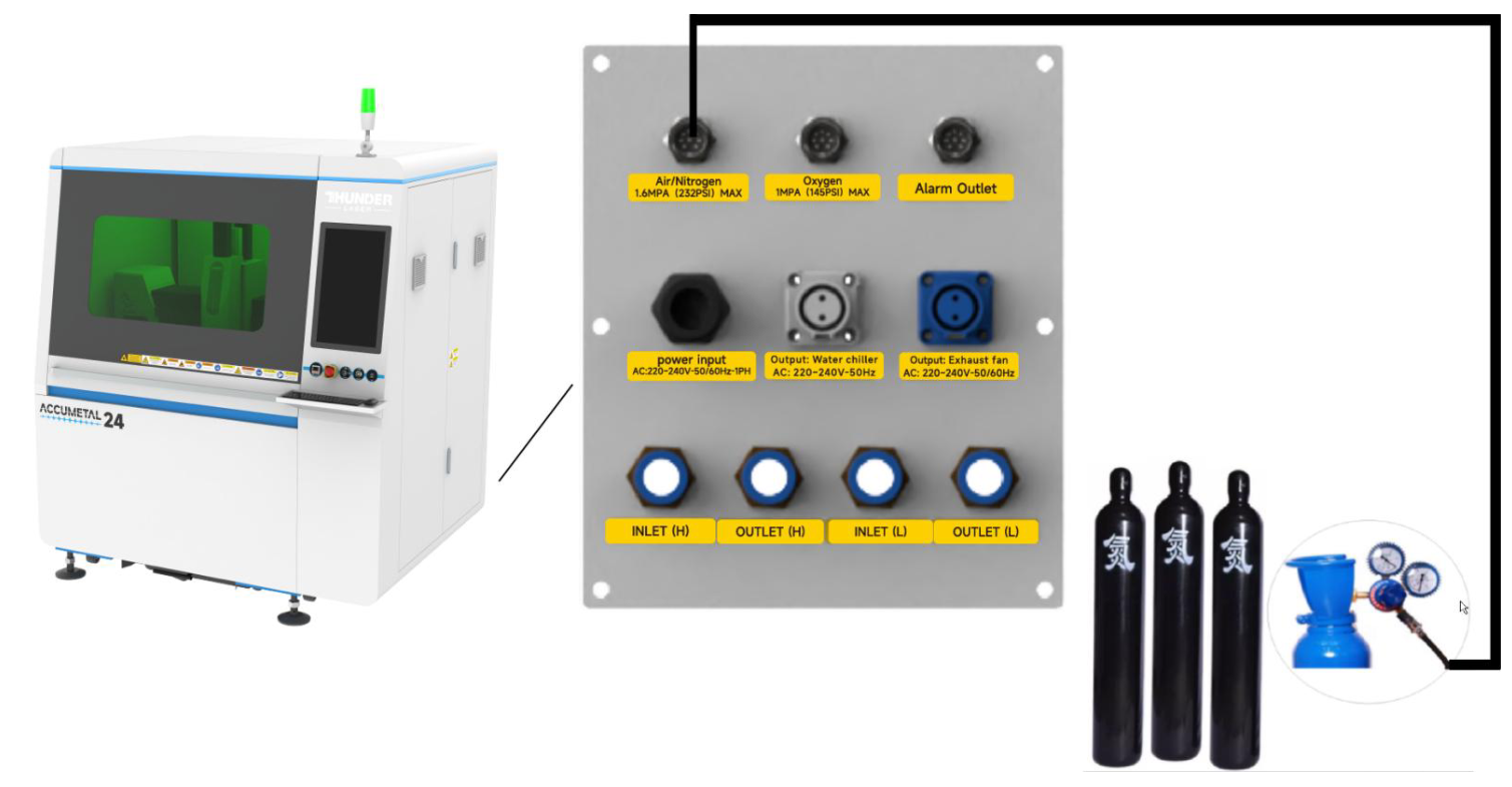
3.6 Electrical Power Connection
This section covers site power requirements, main power wiring, and the electrical connections for the chiller and exhaust fan. Match the installation to the exact machine version and the approved electrical drawing before applying power.
Safety requirements
Provide a dedicated supply circuit and a suitable disconnect. Connect all required protective earth (PE) conductors.
Machine electrical specifications
Below table identifies the machine-side supply, after any stabilizer or transformer. Three-phase voltages are line-to-line values. Verify the equipment nameplates and approved installation data before selecting site wiring or protective devices.
| Item | 1 | 2 | 3 | 4 | 5A | 5B | 6 | 7 | 8 |
|---|---|---|---|---|---|---|---|---|---|
| Machine Version | North America | INTL | Japan (East ) | Japan (West) | North America | North America | INTL | Japan (East ) | Japan (West) |
| Laser Source Power | 1500W | 3000W | |||||||
| Phase | Single-Phase | Three-Phase | |||||||
| Rated Voltage | 220 V | 380 V | |||||||
| Under/Over Voltage Protection | 210-240V | 210-240V per phase | |||||||
| Frequency | 60Hz | 50Hz | 60Hz | 50Hz | 60Hz | ||||
| Standard Chiller | CWFL-1500 BN | CWFL-1500 AN | CWFL-1500 BN | CWFL-3000 BN | CWFL-3000 AN | CWFL-3000 BN | |||
| Exhaust Fan | 1100W centrifugal fan | ||||||||
| Max Power | 9000W | 10000W | 15000W | ||||||
| Max Current | 40A | 22A/ 17A/ 6A (L1/ L2/ L3)(exhaust fan/ laser source/chiller and other) | 30A/ 12A/ 26A (L1/ L2/ L3)(exhaust fan and laser source/ laser source/chiller, laser source and other) | ||||||
| Steady-State Current | 30A | 4A/ 17A/ 4A (L1/ L2/ L3)(exhaust fan/ laser source/chiller and other) | 14A/ 12A/ 17A (L1/ L2/ L3)(exhaust fan and laser source/ laser source/chiller, laser source and other) | ||||||
| Circuit Breaker | 50A | 32A | |||||||
The machine supply must match the specified frequency. A conventional voltage stabilizer or transformer does not convert 50 Hz to 60 Hz or single-phase power to three-phase power.
Site supply and voltage conditioning
The table below identifies the proposed stabilizer and transformer configurations.
| Item | Laser Power | Model Version Machine-Side Voltage | Recommended Stabilizer / Transformer | Input Voltage Range | Output Voltage | Stabilizer / Transformer Input Plug |
|---|---|---|---|---|---|---|
| 1 | 1500W Fiber Laser | North American 220V 1PH | Voltage Stabilizer TND-40 kVA, 1Φ | 180–254 V | 220V | 6-50P |
| 2 | International 380V 3PH | AVR-50 kVA, 3Φ | 350–440 V | 380V | CEE-plug 32A 5p 6h IP44 SHARK | |
| 3 | Japan (East) 380V 3PH | Integrated Voltage-Regulating Transformer SGAVR-50 kVA, 3Φ | 180–230 V | 380V | WF6430 | |
| 4 | Japan (West) 380V 3PH | SGAVR-50 kVA, 3Φ | 180–230 V | 380V | WF6430 | |
| 5A | 3000W Fiber Laser | North America 380V 3PH | SGAVR-60 kVA, 3Φ | 180–230 V | 380V | L15-30P |
| 5B | North America 380V 3PH | SGAVR-60 kVA, 3Φ | 440–510 V | 380V | L22-30P | |
| 6 | International 380V 3PH | Voltage StabilizerAVR-60 kVA, 3Φ | 350–440 V | 380V | CEE-plug 32A 5p 6h IP44 SHARK | |
| 7 | Japan (East) 380V 3PH | Integrated Voltage-Regulating Transformer SGAVR-60 kVA, 3Φ | 180–230 V | 380V | WF6430 | |
| 8 | Japan (West) 380V 3PH | SGAVR-60 kVA, 3Φ | 180–230 V | 380V | WF6430 |
SGAVR denotes the specified integrated voltage-regulating transformer: step-up for items 3, 4, 5A, 7 and 8; step-down for item 5B. 1Φ = single-phase; 3Φ = three-phase. Three-phase input and output values are line-to-line.
Direct connection
Direct connection without a stabilizer or transformer is permitted only when the site supply meets all machine requirements. Do not connect a 380 V machine directly to a 200 V, 208 V, or 480 V supply.
Where an existing site transformer is used, confirm its voltage, phase, neutral arrangement, capacity, and output stability under load. Whether additional voltage regulation is required depends on the complete installation requirements.
Main power connection
Figure below shows the machine main power cable connection. Here the machine is connected to the dedicated external circuit breaker. Identify individual conductors using their labels and the approved wiring diagram.
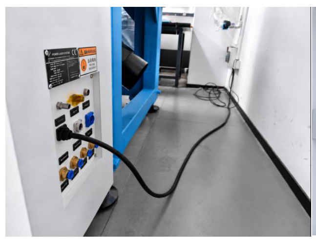
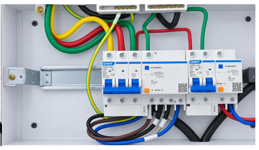
The machine main power cable is supplied without a plug. If a stabilizer or transformer is installed, connect the machine to its OUTPUT terminals and the protected site supply to its INPUT terminals.
| Connection | Requirement |
|---|---|
| Phase conductors | Connect L1, L2 and L3 as shown for a three-phase version. For a single-phase version, use the exact conductor designations in its wiring diagram. |
| Neutral N | Provide N wherever specified. The stabilizer or transformer output must provide the neutral connection specified in the approved wiring diagram. |
| Protective earth PE | Connect PE to the designated protective earth terminal. Do not switch or fuse the PE conductor. |
| Cable termination | Use correctly rated terminals and strain relief. Tighten to the specified torque and enclose all live connections. |
Identify conductors by terminal markings and the approved diagram, not by color alone. Do not copy the terminal positions or conductor colors from an unrelated installation.
Additional site power cable
The toolbox includes an additional power cable with the plug type agreed at the time of order. This cable is intended for the stabilizer or transformer INPUT. Verify its rating against the approved site-side circuit before use. If a hardwired supply is required, a qualified electrician may remove or replace the plug according to local requirements. Terminate the cable in a suitable enclosure with isolation, overcurrent protection, and strain relief.
Chiller and exhaust fan connections
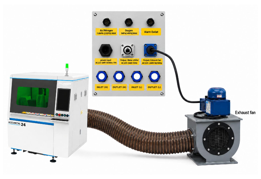
With all supplies isolated, connect the chiller to the designated water chiller output, chiller alarm cable to the alarm outlet and the exhaust fan to the designated exhaust fan output.
The illustrations below show connection locations only. Their printed voltage, frequency, current, and gas-pressure labels are not specifications for every model. Use the labels on the delivered equipment and its approved wiring diagram.
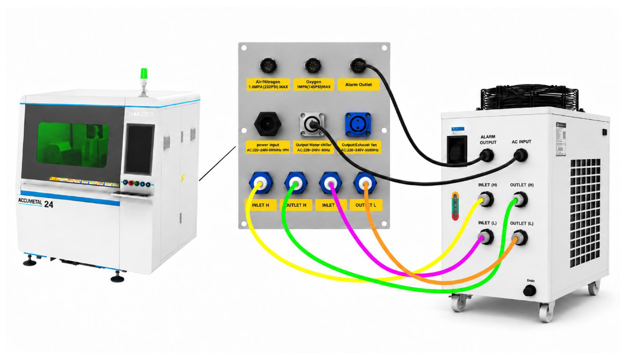
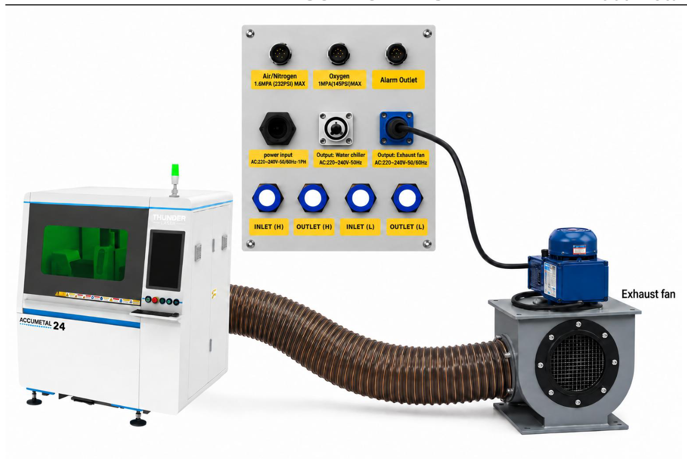
Do not identify an outlet solely by its color or position. Confirm its label and electrical rating. A 380 V machine input does not mean that its accessory outputs are rated 380 V. Do not connect other equipment (e.g an air compressor) or overload these outputs.
Initial energization
A qualified electrician must verify the site supply and, where fitted, the stabilizer or transformer output before energizing the machine. Live measurements require appropriate test equipment and electrical safety procedures. Confirm line-to-line voltages and, where required, line-to-neutral voltages at the designated test points.
Follow the approved startup sequence for the installed equipment. Where applicable, verify phase sequence and motor rotation according to the manufacturer’s instructions. Stop if an alarm appears or any device operates abnormally. Isolate power before correcting wiring.
Before initial energization, make sure the water chiller is already filled with appropriate type and amount of water.
Voltage protection
The machine monitors supply voltage and may prevent startup or interrupt operation when the monitored voltage is outside its configured limits. Use the approved protection settings for the specific machine version.
If voltage protection is triggered, stop commissioning and have the supply, wiring, and stabilizer or transformer output checked. Do not repeatedly restart the machine or bypass the protection. Voltage protection reduces risk but cannot guarantee protection against incorrect wiring, loss of neutral, surges, or every supply fault. Correct the cause before restarting.
Further guidance
For model-specific selection and connection instructions, refer to the guide below and the wiring diagram.
Thunder AccuMetal Series Wiring Diagram
Chapter 4. Startup and shutdown operation tutorial
4.1 Initial Startup Procedure
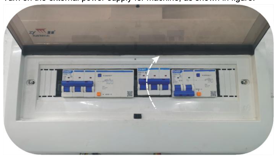
STEP 1: Turn on external power supply
Turn on the external power supply for machine, as shown in figure.
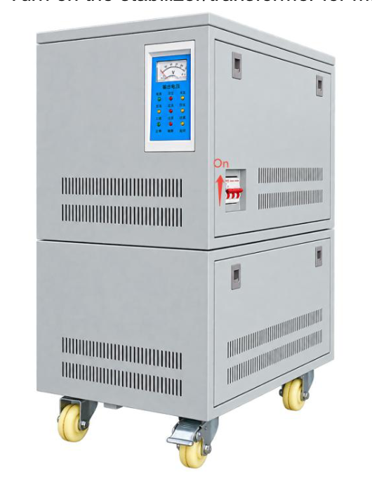
STEP 2: Turn on Stabilizer or Transformer (if applicable)
Turn on the stabilizer/transformer for machine, as shown in figure.
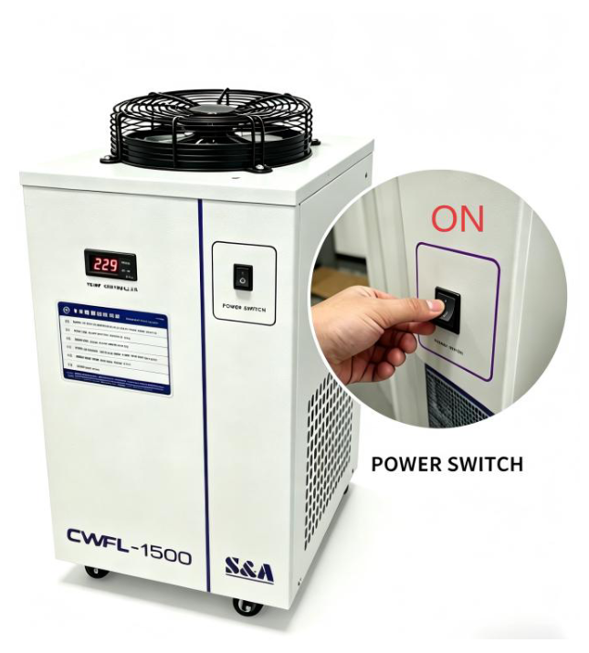
STEP 3: Turn on chiller and exhaust fan
Turn on the chiller, as shown in figures. The Exhaust Fan power cable is connected directly to the machine’s power interface. When the machine starts cutting, the Exhaust Fan will turn on automatically. After the cutting job is completed, the Exhaust Fan will turn off after a preset delay. By default, the Exhaust Fan stop delay is set to 30s.
STEP 4: Turn on main power switch
Rotate the emergency switch clockwise to confirm it was released, then turn the main power switch counterclockwise, as shown in figures.
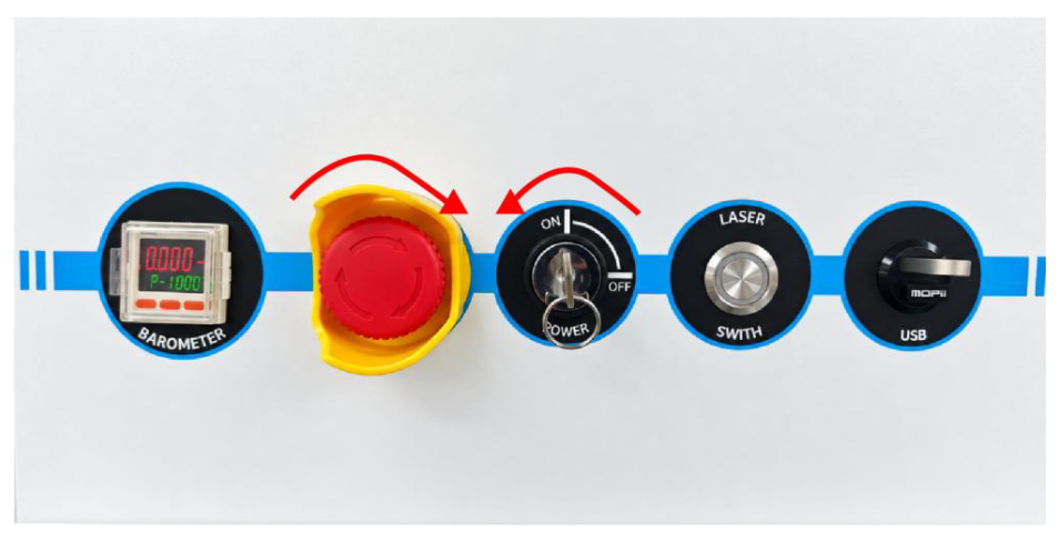
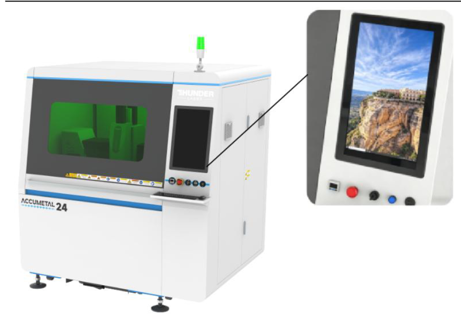
After turning on the main power switch, the circuit system will be power on, and the computer will startup automatically, as shown in figure. Then the Machine startup finished.
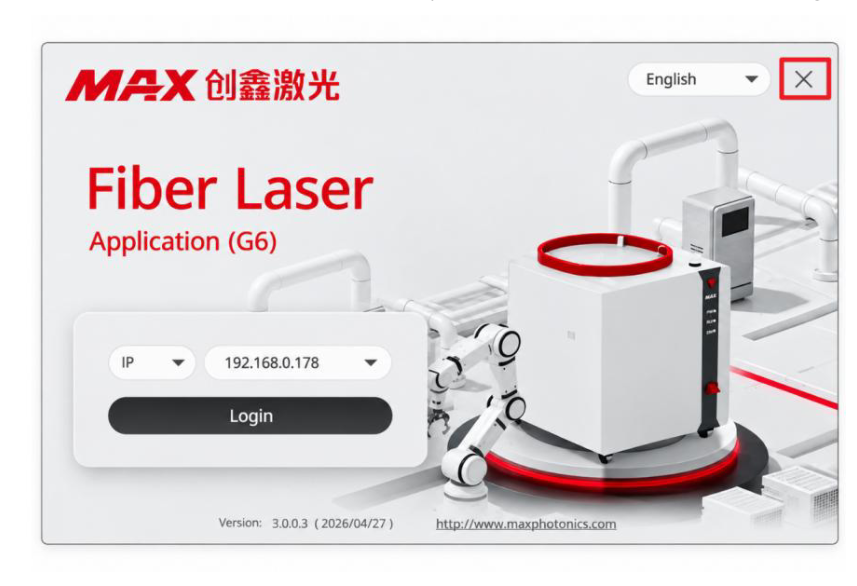
After the machine is powered on, a laser source login window may appear on the computer. This pop-up does not affect machine operation. Simply click the “×” in the upper-right corner to close it.
STEP 5: Turn on laser switch
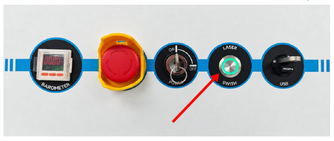
When the laser switch is turned on, the water chiller and laser source will power on simultaneously.
STEP 6: Turn on gas
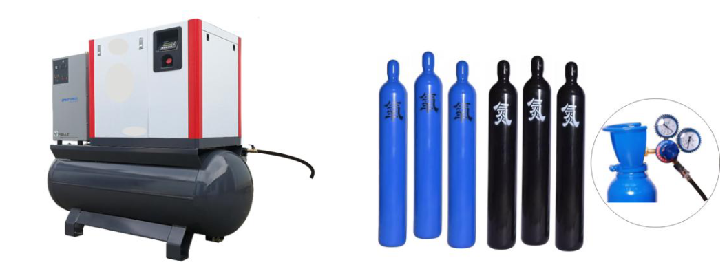
Turn on the gas depends on actual requirements, such as air compressor, oxygen or nitrogen, as shown in figure.
4.2 Shutdown Machine Operations
STEP 1: Shut down computer
Shut down the computer firstly, make sure it finished shut down before doing next steps, as shown in figure.
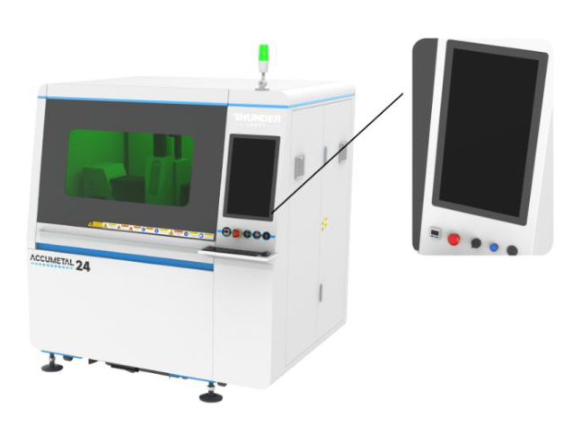
STEP 2: Turn off laser switch
Please make sure the computer was shut down completely, then turn off the laser switch, as shown in figure. When the laser switch is turned off, the water chiller and laser source will shut down simultaneously. There is no need to turn off the water chiller separately.
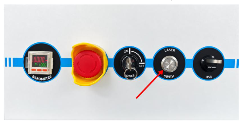
STEP 3: Turn off main power switch
Please make sure the laser switch was shut down completely, then turn off the main power switch, as shown in figure.
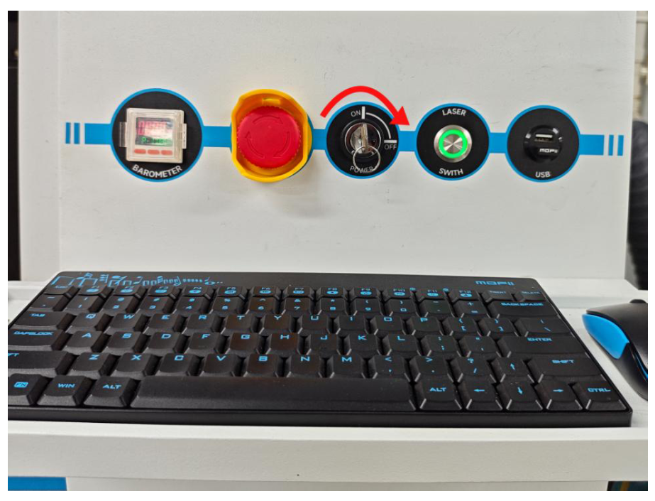
STEP 4: Turn off Stabilizer/ transformer (if applicable)
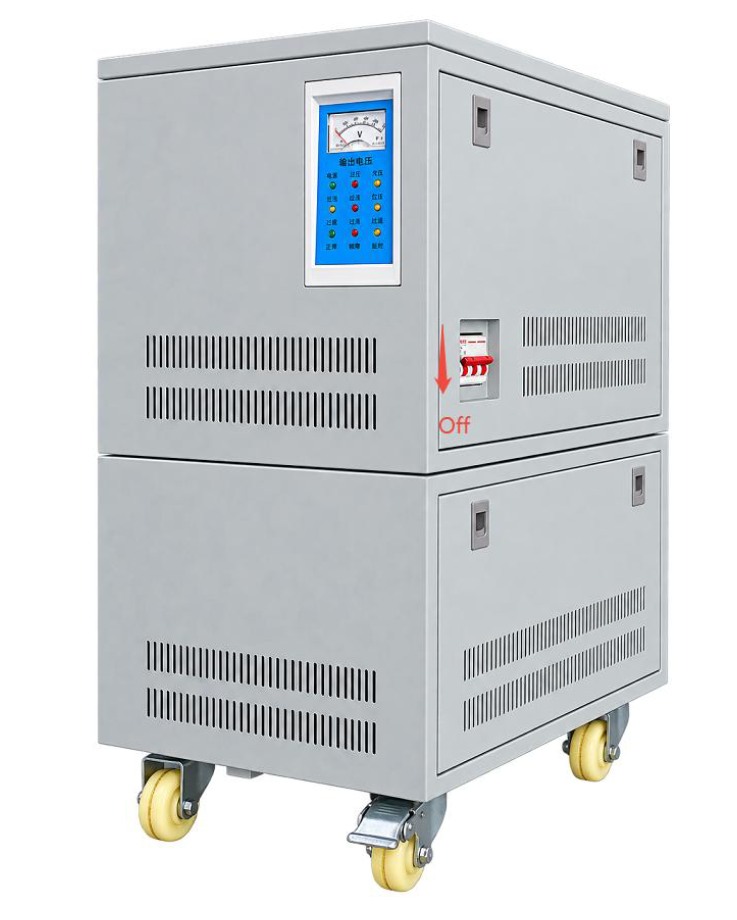
STEP 5: Turn off external power supply
Turn off the external power supply for machine, as shown in figure. Then the Machine shutdown finished.
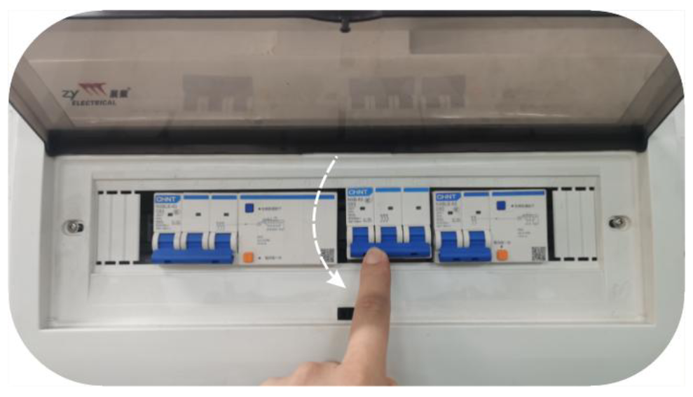
The gas supply from the external equipment can be turned on or off at any time. It does not need to be turned off when the machine is shut down. However, please make sure the gas supply remains on while the machine is processing.
Chapter 5. Software User Guide
5.1 Open the Software and Perform Mechanical Homing
Double-click the icon of the laser processing system control software with the mouse to enter the software, as shown in figure.
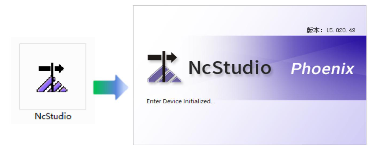
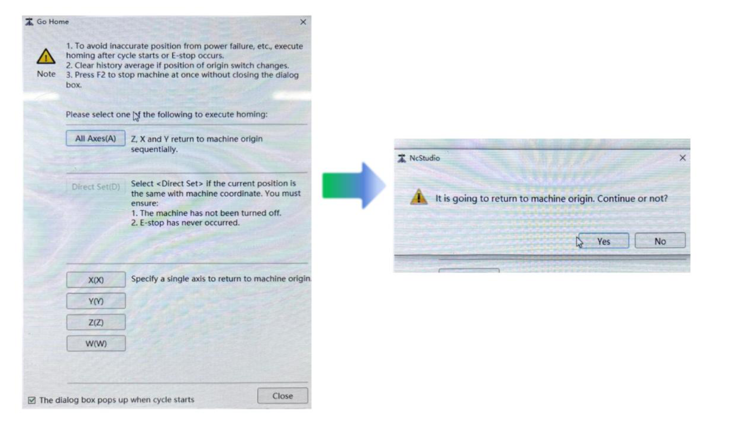
Upon launching the software, a “Go Home” dialog will appear. Click All Axes → Yes to perform mechanical homing, as shown in figures.
Still stuck?
Fastest response times in the industry from our US-based support team.