
Titan - Taking the Laser machine apart to fit through a 30" doorway
⚠ STOP — READ BEFORE PROCEEDING
The upper section of a TITAN machine is heavy and contains precision laser components. Mishandling it can cause serious injury or permanent damage.
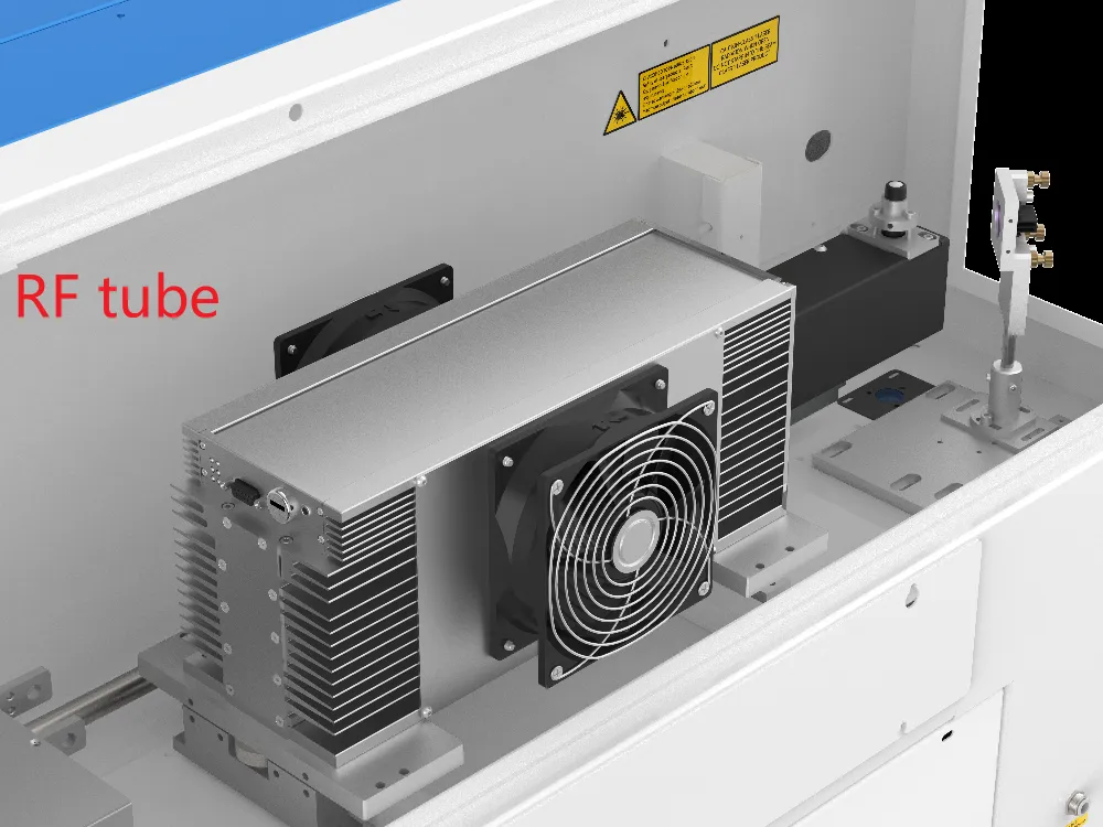
The TITAN contains an RF tube, and the TITAN Pro contains both an RF tube and a fiber laser. These components are easily damaged by impact. Move the machine slowly and avoid striking it against anything.
Before you begin: power the machine off and unplug it, photograph every wiring connection before you disconnect it, use enough people and a properly rated dolly for the weight, and keep all removed screws and terminals organized so the machine can be reassembled correctly.
Separating the Upper Section from the Base to Relocate a TITAN Machine (TITAN & TITAN Pro — 27 / 35 / 51 / 63)
Overview
This article explains how to separate the upper section of a TITAN machine from its fixed base so the machine can be moved through doorways, elevators, or other tight spaces, and then reassembled in its new location. It applies to the TITAN and TITAN Pro in the 27, 35, 51, and 63 sizes. Step 4 and Step 5 include details that differ by size and model, so follow the variant that matches your machine.
| RF | Fiber |
|---|---|
 |
 |
Before You Begin
Power off and unplug the machine, then gather the following tools:
- Phillips screwdriver
- Flathead screwdriver
- Tape or zip ties
- Scissors
- 2.0 mm Allen wrench
- 2.5 mm Allen wrench
- 4.0 mm Allen wrench
- M7 spanner
Photograph every wiring connection before you disconnect it. The photos are your reference for reconnecting the machine correctly in Step 6.
Step 1 — Remove the front door, honeycomb table, and blades
Removing these parts reduces the weight and makes the machine easier to move. Take a picture of the wiring before you disconnect anything.
| Instruction | Reference Image |
|---|---|
| ① Use a Phillips screwdriver and a 2.0 mm Allen wrench to remove the five screws inside the red box. |  |
| ② Disconnect the terminal block connected to the magnetic reed switch (door sensor), then use scissors to cut the cable ties securing the wires. |  |
| ③ Use a Phillips screwdriver to remove the four screws on the front upper door cover. |  |
| ④ Use an M7 spanner to disconnect the yellow GND (ground) wire, then disconnect the two LED strip wires. Finally, cut the cable ties securing the wires with scissors. |  |
| ⑤ Remove the honeycomb table and the blades. | 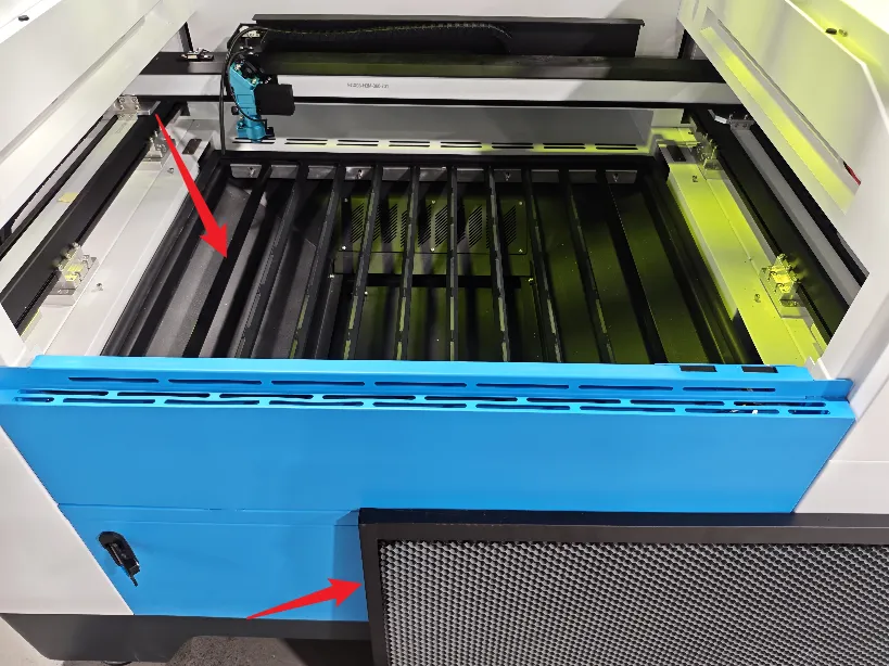 |
Step 2 — Remove the indicator light
Take a picture of the wiring before you disconnect it.
| Instruction | Reference Image |
|---|---|
| ① Use a flathead screwdriver to disconnect the four wires shown below, then free the wires from the gray fixing block. |  |
| ② Use a 2.5 mm Allen wrench to remove the four screws securing the indicator light. |  |
Step 3 — Secure the top lid
Use tape or zip ties to secure the top lid so it cannot open during the move.

Step 4 — Unscrew the center section from the base
First, disconnect the three LED light terminals located at the bottom of the machine base.
| Instruction | Reference Image |
|---|---|
| Left door cover |  |
| Right door cover | 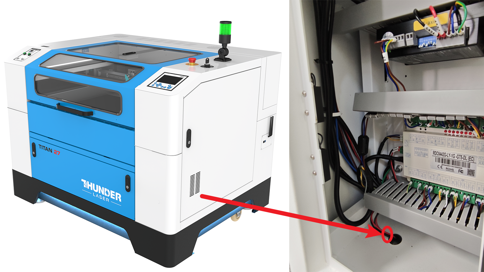 |
Then use a 4.0 mm Allen wrench to remove all the fixing screws that hold the upper section to the base. The screw locations differ by model, so follow the variant that matches your machine.
TITAN 27 & TITAN Pro 27
| Instruction | Reference Image |
|---|---|
| Front door cover (two fixing screws) |  |
| Left and right door covers (two fixing screws each) |  |
| Machine rear (one fixing screw) |  |
TITAN 35, 51, 63 & TITAN Pro 35, 51, 63
| Instruction | Reference Image |
|---|---|
| Front door cover (two fixing screws) |  |
| Left and right door covers (three fixing screws each) |  |
| Machine rear (two fixing screws) |  |
Step 5 — Move the upper section with a dolly
Move the machine's upper section with a dolly rated for its weight. Refer to the picture and the chart below for dimensions and weights.

| Instruction | Reference Image |
|---|---|
| TITAN 27 & TITAN Pro 27 |  |
| TITAN 35 & TITAN Pro 35 |  |
| TITAN 51 & TITAN Pro 51 | 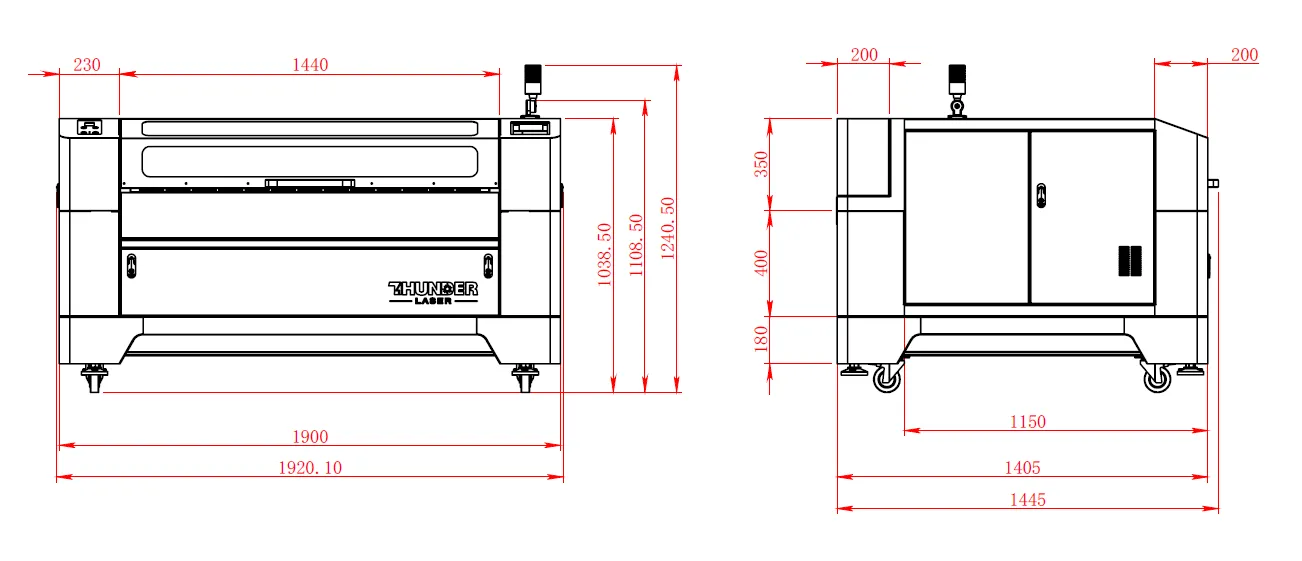 |
Step 6 — Reassemble at the new location
After moving all parts to the new location, reattach the upper section to the base using the screws you removed, then reconnect the terminal blocks. Use the photos you took earlier to confirm every connection is restored correctly.
- Set the upper section back onto the base and install all the fixing screws you removed in Step 4 (front, both sides, and rear).
- Reconnect the three LED light terminals at the bottom of the base.
- Reinstall the indicator light and reconnect its four wires (Step 2).
- Reconnect the front upper door cover: the yellow GND (ground) wire, the two LED strip wires, and the door-sensor terminal block (Step 1).
- Reinstall the front door cover, honeycomb table, and blades.
- Remove the tape or zip ties securing the top lid.
- Confirm all connections match your reference photos before powering the machine on.
If you are a Thunder Laser USA client and still need Technical Support after exhausting the resources in the Knowledge Base, email [email protected] and the Technical Support Team will promptly assist you.
Still stuck?
Fastest response times in the industry from our US-based support team.