
Adding Manual Interior Illumination Control
answer
Step-by-step tutorial for adding a magnetic reed switch to control interior lighting on Odin (and Nova) series Thunder Laser machines.
Overview
Safety: Be sure to observe all safety precautions and deenergize the equipment before performing any work on the machine. Refer to the Odin Series User Manual for guidance.
This is a tutorial on adding a magnetic reed switch to control the interior lighting in Odin series machines. You can do this on Nova, it just differs a bit.
This allows the interior illumination to only come on with the lid closed AND use a magnet to activate them manually. This tutorial is on the Odin.
For Nova series you will attach the sensor to the RIGHT-HAND door safety interlock and the power rail is in the right side electronics bay. Alter this procedure as necessary for Nova.
Please review this documentation in its entirety (even twice) before attempting the modification.
You could also use just about any other 'standard' switch the same way, even an illuminated one (you will have to use a 24v illuminated switch and run a third wire to supply 24vdc to the switch). If you have any questions, please reach out to Thunder tech support.
CAUTION: Using the magnet hack shown in the operation video may also defeat the OEM left-side safety interlock due to its proximity to the magnet. There is another on the right side of the door that should remain operational, but keep this in mind.
Things You Will Need
To successfully complete this modification as defined in this article, you will need the following:
- Stranded 2 Conductor wire, similar to this: https://www.amazon.com/TYUMEN-Electrical-Extension-Flexible-Lighting/dp/B01LZRV0HV/
- A few rows of screw terminal blocks, similar to this: https://www.amazon.com/gp/product/B08NGBQWWT
- A NORMALLY CLOSED magnetic reed switch, similar to this: https://www.amazon.com/MC-38-Surface-Sensor-Magnetic-Switch/dp/B09VKZSNF9/
- A few Cable ties, similar to this: https://www.amazon.com/HAVE-ME-TD-Cable-Ties/dp/B08TVLYB3Q/
- A screwdriver that fits the screw terminals, similar to this: https://www.amazon.com/Screwdriver-Different-Flathead-Screwdrivers-Precision/dp/B08B87RQJ9/
- A Strong magnet, similar to this: https://www.amazon.com/DIYMAG-Refrigerator-Magnets-Hobbies-Industrial/dp/B08HQNVXRG/
Locate 0v14 Wires
Locate the 2 0V14 wires (one for each lamp) on the power rail in the left side electronics bay for Odin, and on the Right side of Nova.

Remove 0v14 Wires
Remove the 2 0v14 wires by depressing the corresponding orange spring-loaded tab.

Prepare Terminal Connector
Snip off 1 row of the terminal block and make sure the screws are out enough to allow the wires to pass into the connector unobstructed.

Bind And Terminate 0v14 Wires
Twist the 2 0v14 wires together and terminate them with the terminal block.

Prepare Wire
Prepare the 2 conductor wire. Hold it up to the terminal locations and verify before cutting.

Connect Wire
Connect the wires, one to the terminal block on the 0v14 wires, and the other to the ground buss on the power rail.

Route Wire
Route the wire to the desired location, in this case (Odin) up to the area of the air assist control. Notice the extra loops of wire left in case it is needed later or to reconfigure. Nova will be similar but happening on the right hand side of the machine.

Terminate Switch
Terminate the wire with the switch using a 2 position terminal block. This is on Odin; Nova will look different because you will be working on the right side.

Mount Switch
Mount the switch onto the existing left-side door interlock switch for Odin, and the Right side switch on Nova.

Tidy Wiring
Tidy up the wiring. Odin is shown.

Check Clearance
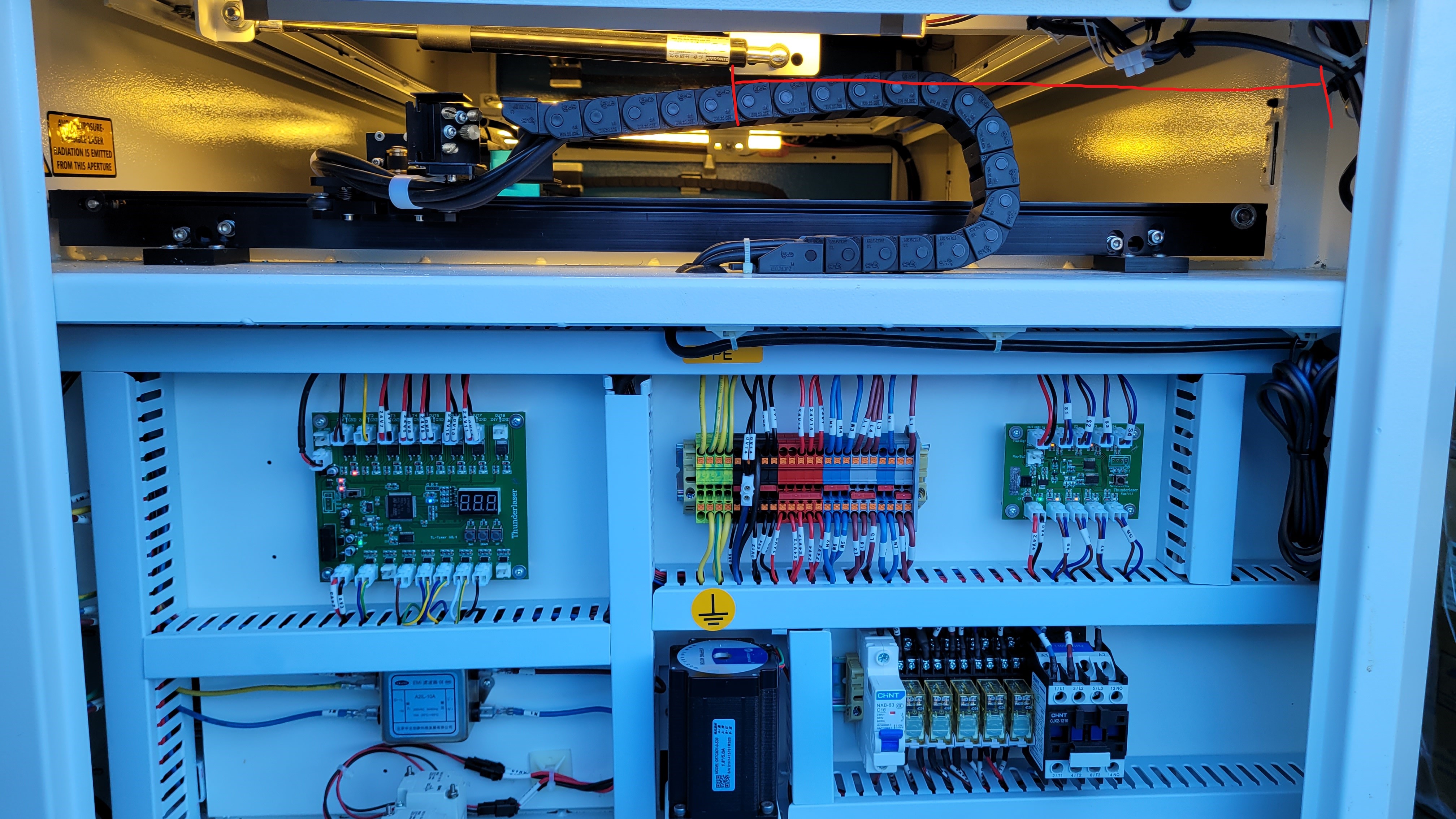
Check the clearances by manually moving the gantry all the way forward to ensure none of the wiring will be in the way. Nova will be similar.
Operation and Use
Here is a short video of the operation of this mod and how to use a magnet to make the lights come on with the lid up (sorry its shaky and crude).
On Nova, you will be putting the magnet on the right-hand side near the added switch.
Still stuck?
No bots, no runaround. Talk to a U.S.-based laser tech who knows your machine inside out.