
Fiber Laser Cutting Guide 1.5kw
Settings, gases and troubleshooting for 1.5 kW fiber cutters
A clean cut comes down to five settings and one habit: change one thing at a time and let the edge tell you which way to go. This guide shows what each setting does, how to pick a gas, and how to fix what you see on the part.
Inside this guide
How a laser cut works
The five core settings
Choosing a gas
Frequency and duty cycle
The three heights
Fixing common problems
Starting settings for 1.5 kW
How a laser cut works
The beam melts a narrow line through the metal, and the assist gas blows that melt out the bottom. Every setting either changes the heat (power, speed, pulsing) or changes how well the gas clears the cut (pressure, nozzle, focus, height).
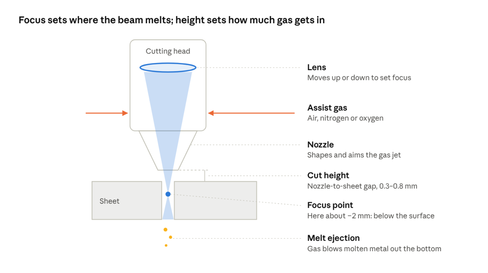
Cutting head cross-section · beam, gas and the two adjustments
The lens moves to set focus; the whole head moves to set cut height. They are two separate adjustments.
The five core settings
Speed, pressure and focus do most of the work. Power usually stays at 100%.
Setting | What it controls | Too high | Too low |
|---|---|---|---|
Power (%) | Peak laser output | Extra heat, wider kerf | Won't cut through; lower speed instead |
Speed(m/min) | How long the beam heats each spot | Beam lags: angled lines, hard beads, may not cut through | Too much melt: rough edge, soft drips, discoloration |
Gas pressure(bar) | Force that blows molten metal out the bottom | Air/N2: rarely a problem. O2: rough, over-burned edge | Air/N2: dross on the bottom edge |
Focus (mm) | Where the beam is narrowest. Minus = into the metal | Toward +: wide spot on top (oxygen style) | Toward −: wider kerf at the bottom so gas gets through (air/N2 style) |
Nozzle (S2, S3, D1.2) | Gas jet type and size | Bigger opening: more gas volume, slower jet | Smaller opening: faster, tighter jet |
S nozzles are single-layer, for air and nitrogen. D nozzles are double-layer, for oxygen.
Thicker metal moves focus further from zero. Air and nitrogen run about −1.5 to −5 mm. Oxygen runs about +5 to +6.5 mm.
Change one setting at a time and cut a short test line after each.
Choosing a gas
Air is the low-cost default for thin metal. Nitrogen is for bright, weld-ready stainless. Oxygen is for thick mild steel.
Air | Nitrogen | Oxygen | |
|---|---|---|---|
Edge finish | Gray, lightly oxidized | Bright silver, oxide-free | Dark oxide, square and smooth |
Dross | Light burr on thicker parts | Little to none | Low on mild steel when tuned |
Pressure | 8–12 bar (115–175 psi) | 12–15 bar (175–220 psi) | 0.5–1.2 bar |
Running cost | Lowest (electricity only) | Highest (high gas use) | Low |
Best for | Stainless, mild steel and aluminum up to about 3–4 mm | Visible, welded or painted stainless and aluminum | Mild steel from about 3 mm up |
Avoid on | Parts that need a bright edge | Thick mild steel (slow and costly) | Stainless and aluminum |
Air quality matters as much as pressure. Use a dryer plus oil and particle filters. Wet or oily air causes burr and fogs the lens.
Check pressure at the cutting head, not the compressor. Dryers and filters can drop 15–30 psi.
Frequency and duty cycle
These two settings pulse the laser on and off. At 100% duty the laser never turns off, so frequency does nothing; most cuts run this way.
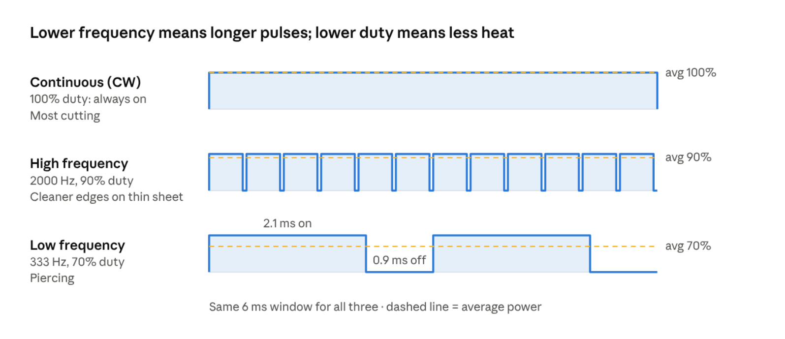
Laser output over 6 ms · continuous vs. high- and low-frequency pulsing
Duty cycle is the share of each cycle the laser is on. Average power = power × duty.
Frequency is how many on/off cycles per second. Lower frequency means longer, heavier pulses.
Pulse cutting (high frequency, 80–90% duty) lets heat escape between pulses: a cleaner edge and less discoloration on thin sheet, small holes and tight corners, at slightly lower speed.
Pulse piercing (100–500 Hz) digs in with each pulse, then pauses so the melt can blow out. A continuous pierce builds a molten pool that erupts up at the nozzle.
Pulse spacing = speed ÷ frequency. Keep it below about 0.1 mm for a continuous cut; wider spacing leaves a dashed line, useful for scoring.
The three heights
Cut height is your main dross control; pierce height decides how long a nozzle lasts.
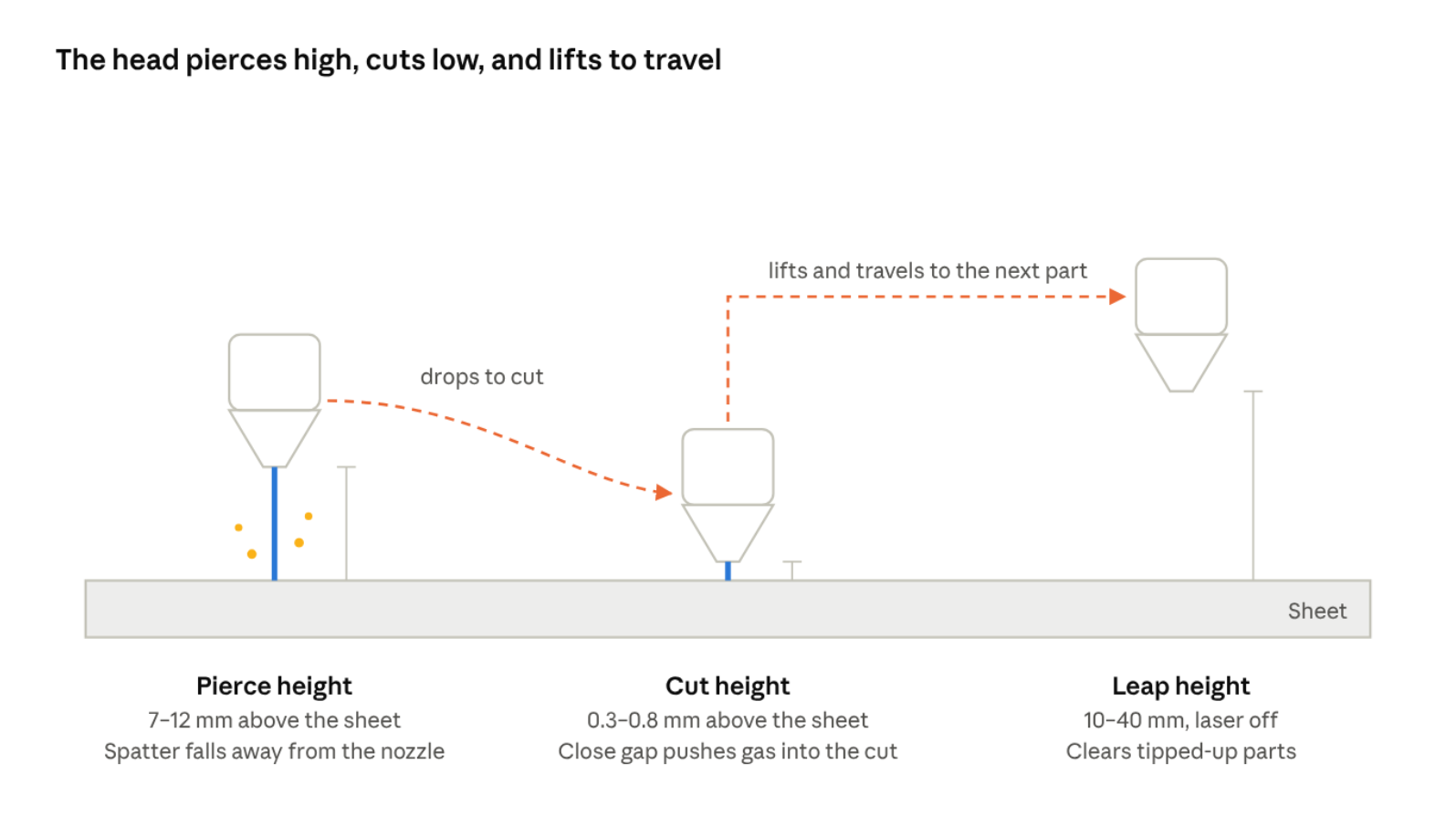
Side view · pierce, cut and leap heights (not to scale)
Height | Lower it | Raise it |
|---|---|---|
Cut height | Cleaner bottom edge; more spatter on the tip | Gas spreads out; more dross |
Pierce height | Faster pierce; spatter reaches the nozzle | Safer nozzle and lens; slower |
Leap height | Faster travel | Clears tipped-up parts |
Focus vs. cut height: focus moves the lens; cut height moves the whole head. Set height for the gas first, then tune focus for the edge.
Pierce delay: too short leaves a gouged start, too long makes a crater. Use a lead-in to keep the pierce mark off the part.
Fixing common problems
Read the edge, then work down the fix list in order, one change at a time.
What you see | Likely cause | What to change, in order |
|---|---|---|
Hard beads on the bottom, lines sweep backward | Too fast | Slow down 5–10% |
Soft drips, rough wide kerf, discolored edge | Too slow or too much heat | Speed up 5–10% |
Dross on the bottom edge (air/N2) | Gas can't clear the kerf |
|
Doesn't cut through | Too fast, or dirty optics | Slow down 10%, then check focus and clean the protective window |
Burned or rounded corners | Full power while the head slows | Turn on or lower the power ramp at low speed |
Dross on one side of the part only | Nozzle off-center or damaged | Center the nozzle (tape shot), replace if worn |
Messy, gouged start | Pierce too short | Add pierce delay, or use a lead-in |
Spatter on the nozzle tip | Pierce height too low | Raise pierce height |
Example: 3 mm stainless on air at 10 bar went from heavy dross to near zero with four changes: S3 to S2 nozzle, focus −3.5 to −4.5 mm, cut height 0.5 to 0.4 mm, and speed 3.0 to 2.5 m/min.
Starting settings for 1.5 kW
Use these for a first cut, then tune with the problem table. ✓ = cut and confirmed on a 1.5 kW machine; the rest are starting points to test.
Material | Gas | Thickness(mm) | Speed(m/min) | Pressure(bar) | Focus(mm) | Nozzle | Cut height(mm) | Verified |
|---|---|---|---|---|---|---|---|---|
Stainless | Air | 1 | 22 | 9 | 0 | S2 | 0.5 | |
Stainless | Air | 2 | 6.5 | 10 | −2 | S2 | 0.4 | |
Stainless | Air | 3 | 2.5 | 10 | −4.5 | S2 | 0.4 | ✓ |
Stainless | Air | 4 | 1.3 | 10 | −5 | S2 | 0.4 | |
Stainless | N2 | 1 | 25 | 15 | 0 | S2 | 0.5 | ✓ |
Stainless | N2 | 2 | 8 | 15 | −1.5 | S2 | 0.5 | ✓ |
Stainless | N2 | 3 | 3.5 | 15 | −3.5 | S3 | 0.5 | ✓ |
Stainless | N2 | 4 | 2.1 | 15 | −4 | S3 | 0.5 | ✓ |
Stainless | N2 | 5 | 1.6 | 15 | −5 | S3 | 0.5 | ✓ |
Mild steel | Air | 1 | 24 | 9 | −0.5 | S2 | 0.5 | |
Mild steel | Air | 2 | 6.5 | 10 | −2.5 | S2 | 0.4 | |
Mild steel | Air | 3 | 2.5 | 10 | −3.8 | S2 | 0.4 | |
Mild steel | N2 | 1 | 26 | 15 | −0.5 | S3 | 0.5 | ✓ |
Mild steel | N2 | 2 | 8 | 15 | −2 | S3 | 0.5 | ✓ |
Mild steel | O2 | 3 | 3.3 | 0.55 | +6.4 | D1.2 | 0.5 | ✓ |
Mild steel | O2 | 5 | 2.0 | 0.58 | +5.7 | D1.2 | 0.3 | ✓ |
Mild steel | O2 | 6 | 1.7 | 0.6 | +5.5 | D1.2 | 0.3 | |
Mild steel | O2 | 8 | 1.3 | 0.55 | +5 | D1.2 | 0.3 | ✓ |
Mild steel | O2 | 10 | 1.0 | 0.6 | +6 | D1.5 | 0.3 | |
Aluminum | Air | 1 | 14 | 9 | −1 | S2 | 0.5 | |
Aluminum | Air | 2 | 4.5 | 10 | −2.5 | S2 | 0.4 | |
Aluminum | N2 | 1 | 15 | 14 | −1 | S2 | 0.5 | |
Aluminum | N2 | 2 | 5.5 | 15 | −2 | S2 | 0.5 |
Settings vary with the laser source, cutting head, lens and gas quality. Aluminum is reflective, so confirm your source has back-reflection protection before cutting it.
Still stuck?
Fastest response times in the industry from our US-based support team.