Leadshine CL1-507-3LS
1. Electrical Information Reference number CL1-507 Minimum Typical value Max unit Continuous output current 3 - 7 A Input power supply voltage +24 36 +48 Vdc Logic input current 7 10 20 mA Pulse frequency 0 - 500 kHz Insulation resistance 100 - - MΩ…

Reference number | CL1-507 | |||
|---|---|---|---|---|
Minimum | Typical value | Max | unit | |
Continuous output current | 3 | - | 7 | A |
Input power supply voltage | +24 | 36 | +48 | Vdc |
Logic input current | 7 | 10 | 20 | mA |
Pulse frequency | 0 | - | 500 | kHz |
Insulation resistance | 100 | - | - | MΩ |
Alarm output logic current | - | - | 100 | mA |
Alarm output voltage | - | - | twenty four | Vdc |
2. Interface definition
A ) Motor and power input port
Pin number | Symbol Name | Description | Note |
1 | A + | A phase motor winding+ | |
2 | A - | A phase motor winding- | |
3 | B + | B- phase motor winding+ | |
4 | B - | B- phase motor winding- | |
5 | +VDC | Input DC power | +24V~ +48V |
6 | GND | Input power ground | 0V |
7 | NC | Empty terminal |
B ) Control signal port
Pin number | Symbol Name | Description | Note |
1 | Pul + | Pulse positive input | You can select 5V or 24V by dialing the code . Note: When the signal is 24V , 5V will damage the input optocoupler. |
2 | Pul- | Pulse negative input | |
3 | Dir + | Positive direction input | |
4 | Dir- | Direction negative input | |
5 | ENA | Enable signal | 5V~24V compatible |
6 | RST | Alarm clear | |
7 | COM+ | Input signal common anode | |
8 | ALM | Alarm | OC mode, maximum pull up 24VDC , 100mA |
9 | PEND/Z-OUT | In-position signal or Z signal, can be selected by SW11 Note: If you need Z signal output, please select the motor and encoder extension cable with Z signal. | |
10 | BRK | Brake control | |
11 | COM- | Output signal common cathode |
3 ) Encoder input port
Pin number | Symbol No. | Description | Note |
|---|---|---|---|
1 | NC | ||
2 | NC | ||
3 | NC | ||
4 | C | ||
5 | VCC | 5V power output, provided by the driver, only used for encoder power supply | |
6 | GND | Encoder power ground | |
7 | EZ+ | Encoder Z phase signal positive terminal | |
8 | EZ- | Encoder Z phase signal negative terminal | |
9 | EB+ | Encoder B phase signal positive terminal | |
10 | EB- | Encoder B phase signal negative terminal | |
11 | EA+ | Encoder A phase signal positive terminal | |
12 | EA- | Encoder A phase signal negative terminal |
Cooling method | Natural cooling or additional radiator | |
|---|---|---|
Use environment | Use occasion | Try to avoid dust, oil mist and corrosive gas |
temperature | 0℃ -50℃ | |
humidity | 40 -90%RH | |
shock | 10~55Hz/0.15mm | |
Storage temperature | -20℃ -65℃ | |
Heavy volume | Approximately 280 grams |
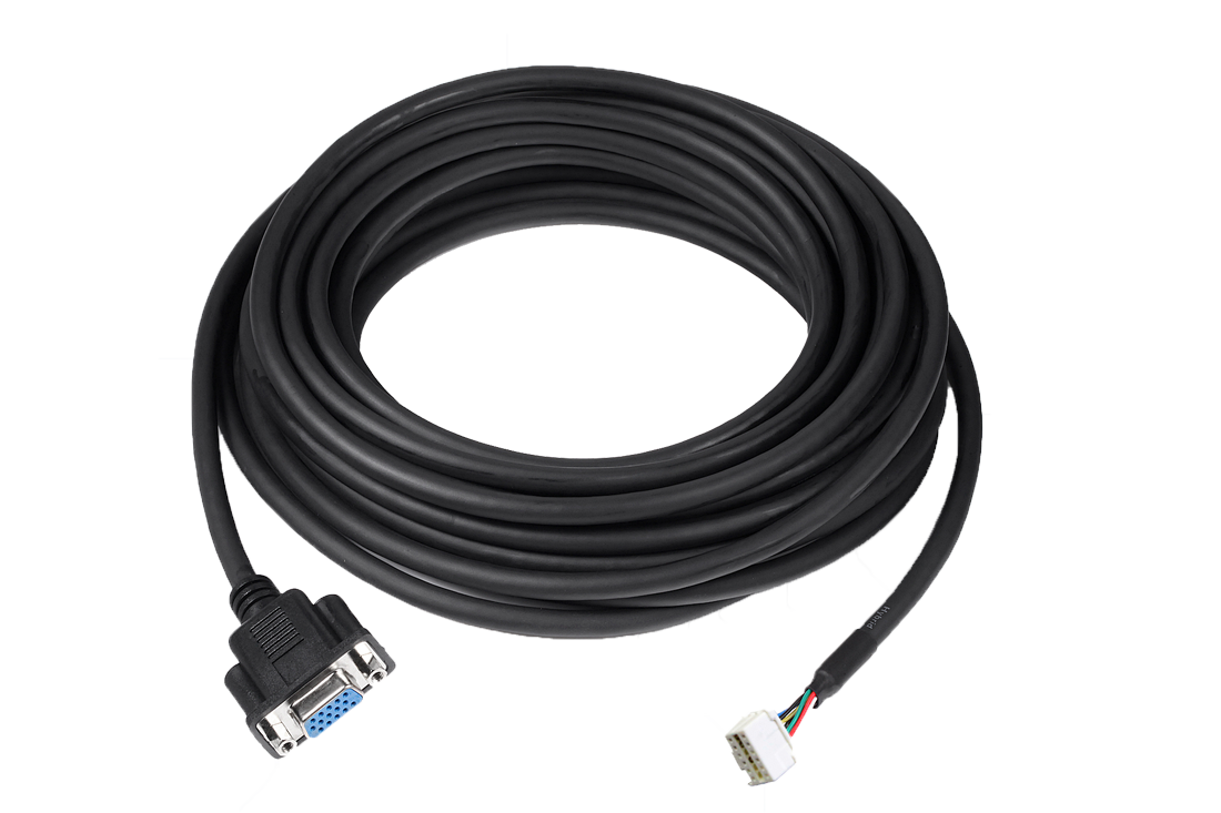
Example Encoder Cable: