
This article has instructions on how to wire your inline exhaust fan so that it comes on with the Laser Switch and to provide power to the Chiller so that you can "Dry Run" the Laser and also ramp the exhaust fan up prior to starting a job.
LightBurn now has start timers built in so the fan can spool up before the job starts. There are settings for end delay time too but leave that at 0 because end delay is controlled by the TL-Timer.
This will change the function of the machine. If you perform this modification you do so at your own risk. You should understand how to work on equipment and double check your wiring. This modification removes the fan from TL-Timer control (automatic) and relies on the operator to control the fan and to turn the chiller on and off manually.
WHILE PERFORMING THIS MODIFICATION, UNPLUG THE MACHINE FROM THE WALL, FLIP THE MACHINE MAIN BREAKER TO THE OFF POSITION, GREEN INDICATOR


What You Will Need
- Small Flat Head Screw Driver
- Phillips Head Screw Driver, P2 size
- Wire cutters/Strippers for 12AWG stranded
- 30 Minutes
- Knowledge of working with Terminal blocks, wiring
What This Will Do
- Chiller will be powered up when the machine is supplied 120v and the Chiller Switch is on. Normally it is powered by the Laser Power switch through main contactor. User will be able to turn the chiller on and off by the switch located on the front of the chiller.
- Fan will be powered up with the Laser Power Switch — Usually the fan comes on at the start of a job and ramps up. The User will be able to control when the fan comes on by using the Laser Power switch.
What the Benefit Is
- Can perform 'dry running' of a job (especially useful on rotary jobs) where you can run the machine with the Laser power switch off and not get a water fault.
- Fan will ramp up and stay running while you have the Laser Power Switch on prior to a job starting and after the job ends until you power the Laser switch off. This can be useful to clear out smoke and smells.
What the Side Effects Are
- Operator has to use the switch on the Chiller to power the chiller on/off.
- Fan will stay running until you power the Laser switch off.
Existing Machine Schematics
- Nova Series v8 AC Power Overview and Diagnostics
- Nova Series DSP TL Timer Mid 2020 Block Diagram v8.3
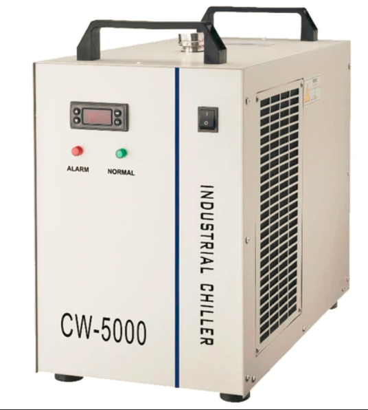
Switch Located at Chiller
(Cw-5000 shown, your model may vary)
Switches Located at the Machine

Existing Wiring on Terminal Blocks
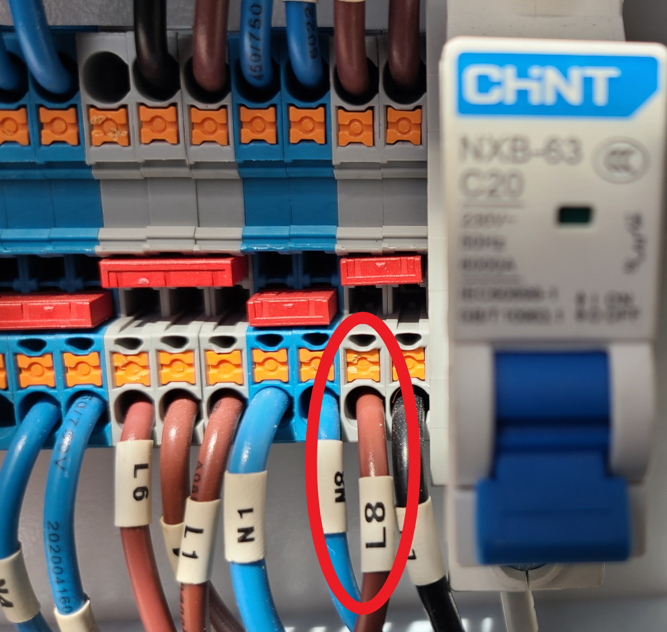
Note the locations of L6 and L8 on the grey terminal blocks:

Chiller Wiring Changes
Before
Chiller is fed by L8 and N8. L8 is controlled by the main contactor which is controlled by the Laser power switch.

After
Fed from Grey Terminal Block and removes 1 wire out of the circuit.
To Make the Change
- Remove both wires from the Main Contactor from the L3 and T3 positions.
- Trace the wire that goes back to an existing grey terminal block and remove it from the grey terminal block by pressing the orange square on the terminal block and pulling the wire out.
- Take the other wire, cut the end off, strip about .25" of copper, and insert into the open spot on the grey terminal block as shown in the picture below.
- Press the orange button, insert wire, and release the orange button.
- Tug on the wire to make sure it is snug.
Fan Wiring Changes
Before
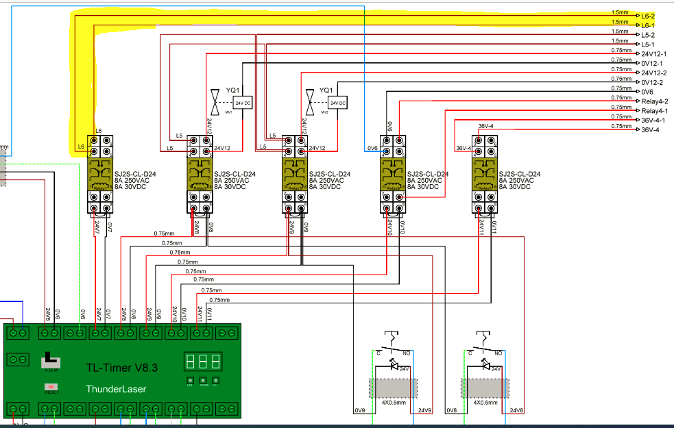
Fan is powered by L6 and N6. L6 is controlled by a relay which is controlled by the TL timer output #7.
After
Move the L6 wires from the relay to the Main contactor terminals L3/T3. The L3 and T3 terminals were originally used by the Chiller.
To Make the Change
- Remove both wires off the relay and then reinstall onto the Main Contactor on L3 and T3.
- You may need to re-locate the 120v feeder wire from the upper terminal block to the lower hole on the same grey terminal block.
- Use a small flathead to press the orange button on the terminal block to release the wire, then re-insert in the other position by pressing the orange button and inserting the wire back into the terminal block.

Final Steps
Double check your wiring and terminations. Then turn the main breaker back on and plug the machine back in.
Test the new functions. Turn the chiller on and off with the switch on the front of the chiller and turn the fan on and off with the laser Switch (main switch must be on as well). If it does not function as expected, please double check everything and then send some pictures and information to [email protected].
Still stuck?
No bots, no runaround. Talk to a U.S.-based laser tech who knows your machine inside out.