
Testing/Adjusting Peripheral Systems using The TL Timer
Preface: This article covers information about the new TL timers in the V8 and V9 generations. Please use the Table Of Contents to get to the pertinent section.
About the TL Timer
The TL-Timer is an IO interface board for Thunder Laser machines. It will control laser machines periphery like air pump, exhaust fan, warning lights, heat alarm detector, electrical locks and lot of other stuff automatically. This will increase the ease of use of your laser machine. Depending on the vintage and version of your TL Timer, not all features will be present.
For TL Timer Version 8 (Found in Nova, Odin and Aurora 1.0)
Here is a video that runs through the channels on the TL timer. You can use the TL timer to manually activate a device for troubleshooting.
Here is the schematic diagram for the V8 (8 channel) TL-Timer:
About TL-Timer Controller Interface and Buttons Description (V8)
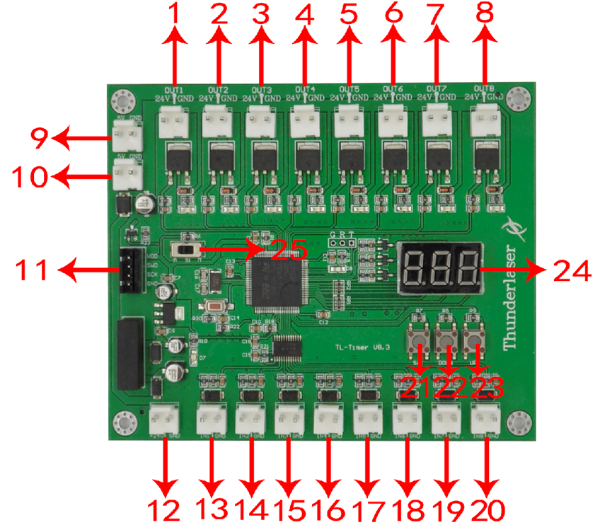
| Item | Item |
|---|---|
| 1. OUT1: Control the green light of warning light; When the machine is not at work, the warning light is in green color | continued: |
| 2. OUT2: Control the red light of warning light; When the machine is working or getting around alarm message on LCD panel, the warning light turns red; | 14. In2, Temperature detection (Nova 51 and Nova 63) |
| 3. OUT3: Control the exhaust fan; Delay shutdown is set to 15 seconds. Factory default settings, change it if required; | 15. In3, Air-assist mode selection; |
| 4. OUT4: Control air assist with "Low volume"; Delay shutdown is set to 10 second. Factory default settings, change it if required) | 16. In4, Control air assist with "Low volume"; |
| 5. OUT5: Control air assist with "High volume"; Delay shutdown is set to 10 second. Factory default settings, change it if required; | 17. In5, Control air assist with "High volume"; |
| 6. OUT6: Control the fire alarm system; When A high temp is detecting on working area, the alarm system will be active, the warning light alarms and the machine stops working immediately; | 18. In6, Temperature detection |
| 7. OUT7: Control the power for rotary device; | 19. In7, Rotary connection state detection |
| 8. OUT8: Spare interface; | 20. In8, Spare interface |
| 9. 5V DC Voltage Power Output 1, control the power for red light pointer. | 21. "Set" button, select each "OUT" interface and confirm the setting; |
| 10. 5V DC Voltage Power Output 2, spare interface; | 22. "DOWN" button, reduce time of delay shutdown; |
| 11. Upgrade interface; | 23. "UP" button, increase time of delay shutdown |
| 12. 24V DC Voltage Power Input; | 24. LED lights display, set the delay time for viewing each interface and enter |
| 13. In1, "Working state" interface | 25. Auto and manual mode switch; |
Location of the V8.x TL Timer
| Machine and Description | Reference Image |
|---|---|
| Nova Series: Right hand side, Lower blue door |  |
| Odin Series: Left hand side, side door |  |
| Aurora 1.0: On top, under the removable panel |  |
TL Timer V8 Operation Modes
Normal use:
-The TL-Timer is selected Auto mode as factory setting as set by the switch marked as item 25.
-Under Auto mode, when the laser is not at processing a job, the applicable outputs will be off; When the laser is processing a job, the applicable outputs start, after the job finished, the applicable outputs will stop after the preset times for each channel elapses.
-Under Manual mode, when the laser is powered on, the air assist and exhaust fan will be on all the time.
-Each "OUT" interface has a freely adjustable delay time from 0-99 seconds.
Set up delay time:
Generally, there's only need to set up the delay time for air assist and exhaust fan, so they can be delay to shutdown according to your need. The default for air assist is 10 second, and for exhaust fan is 15 second.
Click "Set" button to select from OUT1 to OUT8 interface and the LED light display will show you the delay time in second for each interface. On each interface, click "down" or "up" button you can change the value, then click "Set" button to confirm and go into the next interface. On the OUT8 interface, click again the "Set" button, the display will be off and exit the delay time setup.
For TL Timer Version 9.X (Found in Aurora 2.0 and Bolt)
Here is a video that runs through the channels on the TL timer. You can use the TL timer to manually activate a device for troubleshooting.
Here is the schematic diagram for the V9 (11 channel) TL-Timer:
- Aurora 2.0 Series Wiring Diagram TL Timer v9.3
- Thunder Bolt Tl Timer V9.2 Wiring Diagram September 2023 aka Schematics
- Thunder Bolt Tl Timer V9.3 Wiring Diagram September 2023 aka Schematics
- Thunder Bolt Tl Timer V9.4 Wiring Diagram September 2023 aka Schematics
- Thunder Bolt Plus and Pro Tl Timer V9.4 Wiring Diagram December 2023 aka Schematics
About TL-Timer Controller Interface and Buttons Description (V9)
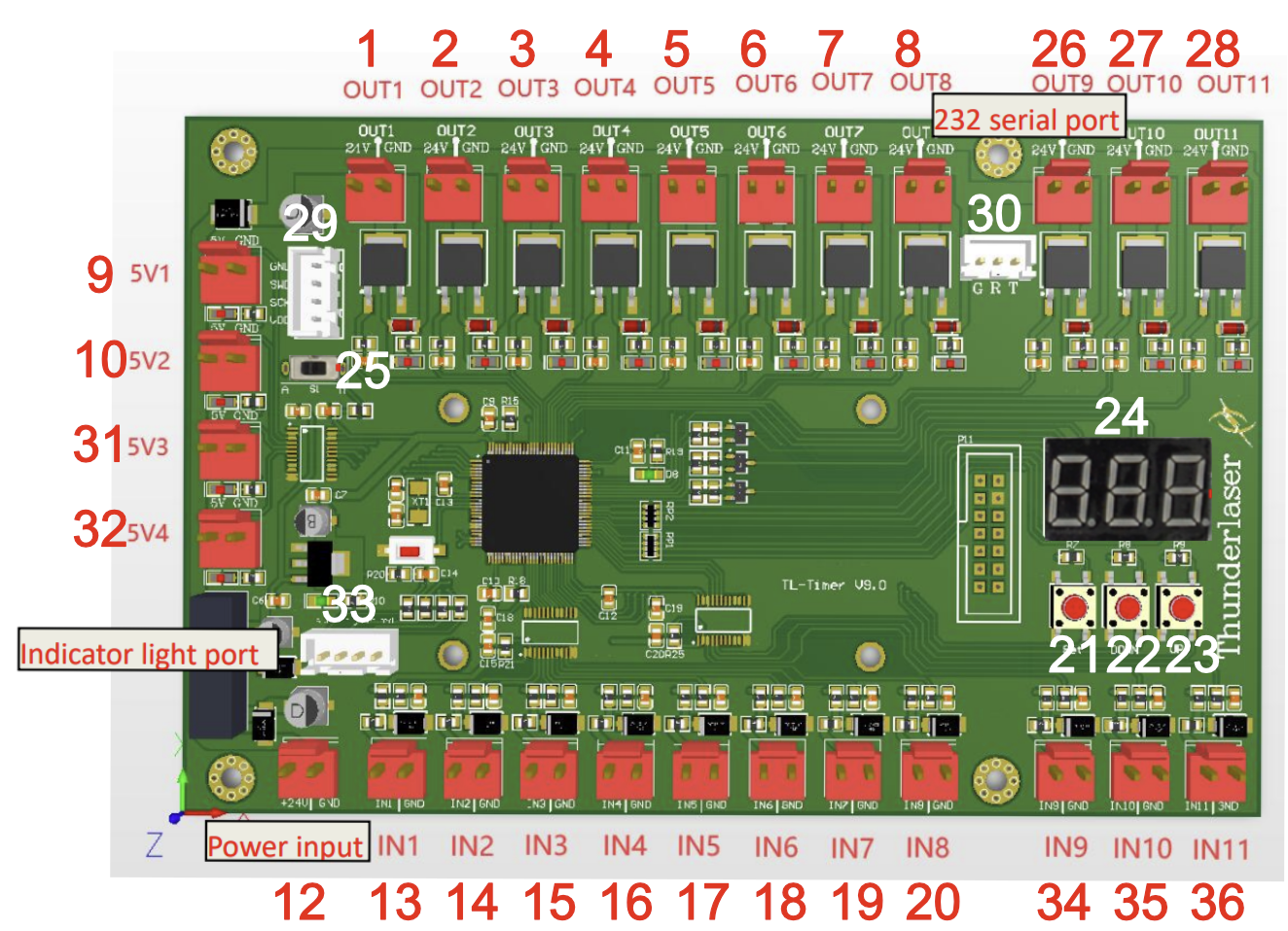
| Item | Item |
|---|---|
| 1. OUT1: Control the green light of warning light; When the machine is not at work, the warning light is in green color | continued: |
| 2. OUT2: Control the red light of warning light; When the machine is working or getting around alarm message on LCD panel, the warning light turns red | 20. In8, Spare interface |
| 3. OUT3: Control the exhaust fan; Delay shutdown is set to 15 seconds. Factory default settings, change it if required | 21. "Set" button, select each "OUT" interface and confirm the setting; |
| 4. OUT4: Control air assist with "Low volume" (If Applicable) | 22. "DOWN" button, reduce time of delay shutdown; |
| 5. OUT5: Control air assist with "High volume" (If Applicable) | 23. "UP" button, increase time of delay shutdown |
| 6. OUT6: Spare interface | 24. LED lights display, set the delay time for viewing each interface and enter |
| 7. OUT7: Control the power for rotary device | 25. Auto and manual mode switch; |
| 8. OUT8: Spare interface | 26. OUT 9 Control the X/Y/Z axes and laser power supply's power |
| 9. 5V DC Voltage Power Output 1, control the power for red light pointer. | 27. OUT 10 LED lamp dimming control |
| 10. 5V DC Voltage Power Output 2, spare interface | 28. OUT 11 spare |
| 11. Upgrade interface | 29. Fan Board interface Port (If Applicable) |
| 12. 24V DC Voltage Power Input | 30. Ruida DSP Interface Port (If Applicable) |
| 13. In1, Laser Pre-Ionization | 31. 5V DC Voltage Power Output 3, spare interface |
| 14. In2, Spare Interface | 32. 5V DC Voltage Power Output 4, spare interface |
| 15. In3, Laser Temperature | 33. Indicator Light Port (If Applicable) |
| 16. In4, Spare | 34. IN9 E-Stop Control |
| 17. In5, Control air assist with "High volume" | 35. IN10 E-stop Control |
| 18. In6, Temperature detection (If Applicable) | 36. IN11 Spare |
| 19. In7, Laser Supply Voltage Detection |
Location of the V9.x TL Timer
| Machine and Description | Reference Image |
|---|---|
| Bolt - Left Side of Machine |  |
| Aurora - Top of machine |  |
TL Timer V9 Operation Modes
Normal use:
The TL-Timer is selected Auto mode as factory setting. The manual mode does nothing on the V9 TL timer currently.
Each "OUT" interface has a freely adjustable delay time from 0-99 seconds.
Set up delay time:
Generally, there's only need to set up the delay time for air assist and exhaust fan, so they can be delay to shutdown according to your need.
For Aurora Exhaust:
Click "Set" button to select from OUT1 to OUT8 interface and the LED light display will show you the delay time in second for each interface. On each interface, click "down" or "up" button you can change the value, then click "Set" button to confirm and go into the next interface. On the OUT8 interface, click again the "Set" button, the display will be off and exit the delay time setup.
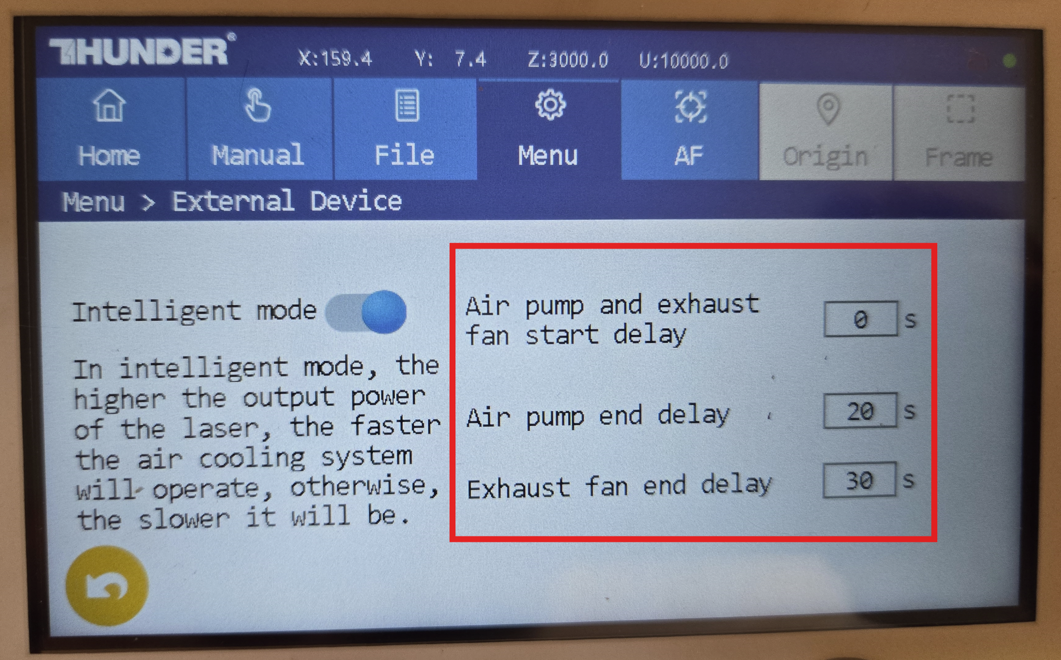
For Bolt Exhaust and Air Assist:
Use the "External Devices" Screen on the Menu of the Laser Machine Control panel to set the start and End Delays for the Exhaust and Air Assist.
| Menu Options | External Devices Screen |
|---|---|
 |
 |
Still stuck?
Fastest response times in the industry from our US-based support team.