
Preface: This article covers how to adjust the 48V power supply voltage for the Thunder Bolt DC 30W RF tube. Power must be on the machine and the Laser must complete the startup sequence.
Warning: This procedure requires work to be done near live voltage. Take proper precautions.
Quickstart Video
Complete Guide
Tools you will need:
- Multimeter
- P1 Phillips Head Screw Driver
- Doorlatch Key
Procedure
1. Locate the Power Supply
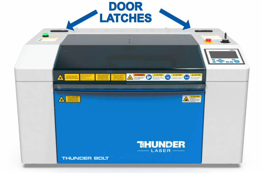
You will need to access the back of the Thunder Bolt Laser where the LPSU and Tube are. Unlock and unlatch the two latches that keep the tube door closed.
 |
 |
| Unlock and Unlatch the Rear Door | Locate Power Supply on Back of Machine |
2. Observe the Power Supply
The power supply is on the left side of the back of the machine. It should have a green Light on it to indicate that it is On and Outputting. Take note of the terminals and devices pointed out below.

3. Measure the Output and Adjust
Use the multimeter to measure the DC output on the V+ and V- terminals. Use the screwdriver on the Trim Pot to adjust the voltage. Small turns clockwise to increase, Small Turns counter-clockwise to decrease.
 |
 |
| Measure with Meter | Adjust with Screw Driver on Trim Pot |
Adjust the voltage until it is between 47 and 49 VDC. Try to get closer to 48V if possible.
Reference Articles
How To Use A Multimeter
Still stuck?
No bots, no runaround. Talk to a U.S.-based laser tech who knows your Bolt inside out.