
Preface: This article covers how to make a Test cable to be able to Test Pulse an RF tube in an Odin or Bolt Laser.
Quick Start Video
How to make and use the test cable
Complete Guide
How to Make the Test Pulse Cable
Tools You Will Need
- Wire Strippers
- RJ45 8 Pin Ethernet Patch cable w/T-568B termination
- Ferrule and Crimper (Optional)
What is a T-568B termination for an Ethernet Cable
The cable you select should have the wires in the following order to meet T-568B requirements. If you have a different cable, it will still work but you will need to ignore the wire colors and go by the Pin Out number only.
Pin. Color
- White Orange
- Orange
- White Green
- Blue
- White Blue
- Green
- White Brown
- Brown
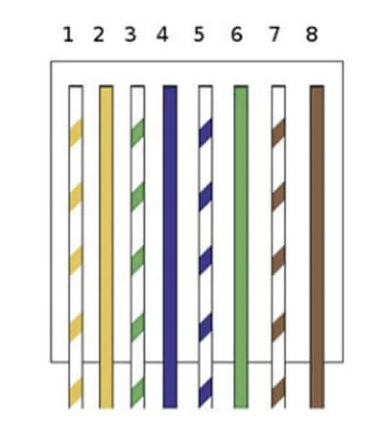
Cable Connections
Pins 1, 3 and 7 should be shorted together. You can use a wire ferrule to crimp them together, solder them, twist and tape etc. You can even use a jumper block if you have one. These wires will not be connected to anything else.
Pin 8 will then be tied to CN5 Pin 1 GND terminal. It is recommended to use the spare green terminal block in CN6. Connect the brown wire to the terminal.
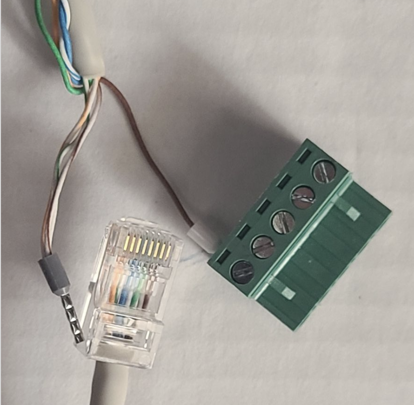
Pro Tip: Break the Ethernet Cable Retainer Tab off the Ethernet end. This will make the cable easier to remove after testing.
The Test
Warning: This test, if successful, will fire the laser at 100% power and bypasses interlocks. You should take the necessary safety precautions when performing this test.
Initial Setup
- Power up your machine
- Remove the lens from your machine
- Place a piece of scrap material (like a wood plank) under the laser head
- De-focus a few inches from the head
- Unplug the Ethernet connection from the Laser Tube
- Unplug CN5 from the Ruida Controller
Test Fire
- Plug the test cable into CN5
- Plug in the cable to the Tube
- Quickly inspect if the tube fires and unplug the cable
- Return machine back to stock. Power off the machine and then plug in machine CN5 and machine Ethernet connections
Still stuck?
No bots, no runaround. Talk to a U.S.-based laser tech who knows your Bolt inside out.