
Rotary Axis no motion troubleshooting
Step-by-step guide to diagnosing why a rotary will not spin on Nova, Bolt, and Odin series Thunder Laser machines.
Preface: This guide will walk you through determining a possible reason as to why your rotary will not spin and is applicable to Nova, Bolt and Odin series machine. If you complete this guide without a definitive cause, please email [email protected] and summarize what you completed.
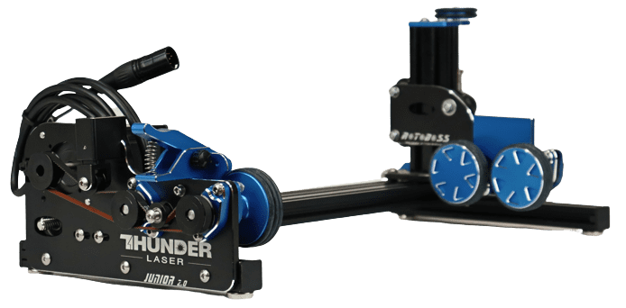
The Thunder Laser Machines will operate a rotary different than other brand machines. We currently use a 7 Pin connector that tells the Ruida controller when a rotary is plugged in and when the rotary should be powered.
This will be some of the easier things to check that may be the cause.
Check the Rotary Cable Connector
Check for bent pins or pins that have retracted. If the pin is slightly bent, bend it back in place and try to plug in.

If you are unable to resolve, send a picture of the connector pins to [email protected]
Check the Dip Switch Settings
The driver is located on the Rotary, it is integrated into the motor. Look for the blue area with the little white switches on it.
Rotoboss Low/Junior/Boss | Rotoboss Talon | Rotoboss Talon Pro |
|---|---|---|
![]() | ![]() | ![]() |
*Dip Switch #5 controls the Clockwise and Counter Clockwise rotation of the motor. If your rotary needs to be reversed, unplug it, swap the position of Dip Switch #5 and plug it back in and test.

Verify that your rotary settings are in range in Lightburn
In Lightburn, Open up the Rotary Setup menu and verify that the settings are read from the machine and that they are within normal values:
If the steps are set to 360....definitely an issue. The values will depend on which rotary you have.
Jog the rotary from the Machine
Try to jog the rotary U Axis from the machine controller after updating Steps and Roller Diameter.
Older Ruida Screen | Newer Ruida Touch Screen |
|---|---|
![]() To jog, press the MENU button on the controller, scroll to "U move" and then use the left and right arrows to jog to rotary. | ![]() Use the physical buttons at the bottom of the screen or go to the MANUAL tab, unlock the nudge buttons and use the soft keys to jog the rotary (You may need to adjust your nudge value, as shown is 100mm) |
Bolt Screen Rotary Indicator
On your Bolt series machine, check for this indicator to let you know that the machine sees that a rotary is plugged in.

Power on the machine. This guide assumes that the 36V power supply is working if the X, Y and Z axis (The laser head and honeycomb bed) are able to move around.
Check for Green Power Status LED
On the rotary motor Driver, look for the green power LED to be illuminated.
Rotary Unplugged from Machine | Rotary Plugged into the Machine |
|---|---|
![]() Green LED is for PWR not illuminated | ![]() Green LED for PWR is Illuminated |
If the Green LED is off, the go to the next step in this section
Check for the Power Relay Activation: Nova Series
Open the lower blue door(s) on the right hand side of your machine to find the relays.
There are 5 relays, the rotary is the furthest to the right
Rotary Unplugged from the Machine | Rotary Plugged into the Machine |
|---|---|
![]() | ![]() |
If the Green LED is on, then the relay is activating. Power off the machine and check the tightness of the terminations at the top of the relay. If that does not fix it then email [email protected] with a summary of what you have completed
If the Green LED is off, the go to the next step in this section
Check for the Power Relay Activation: Odin Series
Open the left side door on your machine to find the relays.
There are 5 relays, the rotary is the furthest to the right
Rotary Unplugged from the Machine | Rotary Plugged into the Machine |
|---|---|
![]() | ![]() |
If the Green LED is on, then the relay is activating. Power off the machine and check the tightness of the terminations at the top of the relay. If that does not fix it then email [email protected] with a summary of what you have completed
If the Green LED is off, the go to the next step in this section
Check for the Power Relay Activation: Bolt Series
There are 4 relays. The rotary relay is 2nd from the top.
Rotary Unplugged from the Machine | Rotary Plugged into the Machine |
|---|---|
![]() | ![]() |
If the Green LED is on, then the relay is activating. Power off the machine and check the tightness of the terminations at the top of the relay. If that does not fix it then email [email protected] with a summary of what you have completed
If the Green LED is off, the go to the next step in this section
Check TL Timer Input\Output Operation: Nova\Odin Series
This is for the Nova/Odin Series with 8.xx TL Timer. The output will be Channel 7 with wire OV11.
Rotary Unplugged from the Machine | Rotary Plugged into the Machine |
|---|---|
![]() | ![]() |
If the Red LED is on, then check the tightness of the connections on the bottom of the relay in the above step. If the Red LED is still off off after tightening the connections, then try this
Check TL Timer Input\Output Operation: Bolt Series
This is for the Bolts Series with 9.xx TL Timer. The output will be Channel 7 with wire OV9. The input from the Ruida controller comes to the TL Timer through the RTlink
Channel 7 LED OFF | Channel 7 LED ON |
|---|---|
![]() | ![]() |
If the Red LED is on, then check the tightness of the connections on the bottom of the relay in the above step. If the Red LED is still off off after tightening the connections, then try this
Manually Activate Rotary Relay
4. Use TL Timer to Manually Turn on the Rotary
Use this article to set the TL Timer board to turn on Channel 7 which should energize the Red LED for OUT7, Energize the Relay to provide power to the Rotary Socket and then will Turn on the Green LED on the Rotary Driver like what was mentioned in above sections. (rotary must be plugged into the machine)

Please email [email protected] with a summary of what you have completed.
Simulate Pin6 and Pin7 of Rotary Cable
Bend a paper clip so that the legs are the same length. Insert into the machine rotary port as shown into Pins 6 and 7. Check that the Rotary Relay and TL timer LED's light up. If this is the case, then most likely your Rotary Cable has a broken Pin6 to Pin7 connection internally that needs to be replaced.

This section will check some of the signals that go between the Ruida Controller and TL Timer
Rotary Cable Pin6 and Pin7
On the rotary connector, Pin 6 and Pin 7 should be tied together internally. This connection can fail so we need to check it.
Using a multimeter, check the OHMs to be under 2 OHM or for the audible continuity signal that pins 6 and 7 are jumpered together.

If Pins 6 and 7 are jumpered (Low Ohms, Beep from meter), goto the next step in this section
If Pins 6 and 7 are not jumpered, please email [email protected] with a summary of what you have completed.
Ruida Controller to TL Timer
Lets check the Ruida input for rotary connection active on IN1 on the Ruida Controller Connector CN2
Unplug CN2 from the Controller:

Unplug this connector from the TL timer Board for TL Timer Input 7:

Use a multimeter to measure the continuity between IN1 and GND on the green Ruida Connector.
Rotary Unplugged:
CN2 connector PIN IN1 to CN2 Connector GND - Open
Rotary Plugged into the Machine:
CN2 connector PIN IN1 to CN2 Connector GND - Continuity, low Ohms, Audible tone on multimeter if selected
If the IN1 to GND Shows continuity, then proceed to the next step of "Last thing to check".
If the IN1 to GND Shows open, then email [email protected] with a summary of what you have completed.
Last thing to check
Ok so this is a short blurb but the amount of work is not as short:
Inspect the wiring of all the plugs\connectors\devices mentioned in the article above. Visually inspect that the wire ferrules\crimps are on the wire conductor and not the wire insulation. Make sure screw terminals are tight.
Plug everything back in when you are done testing.
In order to force the Laser Ruida Controller to run in Rotary Mode and to get the TL Timer to provide power to the rotary, we can install a jumper wire between GND and IN1 on CN2 of the Ruida controller as shown by the Red Line on the image below. Power off the machine while installing the jumper. Plug CN2 and the rotary back in for use.
Note: In order to run a normal non rotary job, you must remove the Jumper wire. The Jumper Wire must only be in place when you want to run a rotary job.

Below are some useful graphics and links that are compiled here because they may be helpful as you troubleshoot.
This is the connector on the rotary cable.

This is the port on the laser machine.

This is a simplified drawing for Nova and Odin Series Machines Rotary Wiring for 7 Pin XLR (Trimmed down from the main schematics)
(note that the pinout is shown for the Cable End, likewise from the rear of the Port)
Rotary Port to Ruida Controller | TL Timer to Power Relay |
|---|---|
![]() | ![]() |
Still stuck?
Fastest response times in the industry from our US-based support team.


