
Thunder Bolt Ramp Test and Setting Autofocus Height for Best Engraving Results
Applies toBoltTopicGeneral
Preface: This article will cover the steps to perform a ramp test to be able to set the autofocus height and the length of the manual focus tool. For this procedure, it is assumed that you are already connected to the machine and ready to run. This article was written with screenshots from Lightburn 1.4.00 if you are using a different version then your screens may look different.
Tools and Materials that you will need:

1.5mm Allen Wrench
Manual Focus Tool
Lightburn installed and configured
Consistent Material (MDF as an example)
Before you begin:
Let's start at your computer that is connected to your Bolt and take a backup of your Machine Settings.
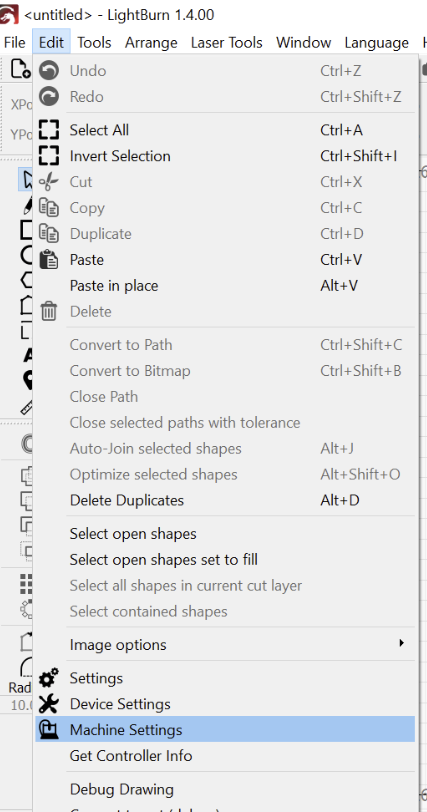
In Lightburn, go to Edit>Machine Settings (will be under Laser Tools>Machine settings if you are on v2.0 or newer Lightburn)
Then use the "Save to File " button to save a copy in your desired location ( save the file with _Original attached to the name). Do not close out the machine settings window, it will be used in the first step of the process of doing the ramp test.
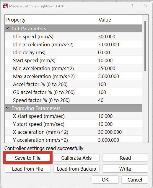
A Bit more info on settings that can be backed up with Lightburn:
The Process:
Follow these steps in order. Each step assumes that the previous step was completed.
Step 1: Reset the Focal Length
While still in the Machine Settings, scroll down until you find the value for "Focal Distance" under the Miscellaneous. In this case, the value is currently 1.7mm. Set the value to 0.00mm and then use the "Write" button to send the change to the controller.

Step 2: Enable Z Moves in Lightburn
We need to enable Z moves so that the honeycomb table position can be changed on the fly for the ramp test.
In Lightburn, select the icon that is a Wrench and Screwdriver, highlighted below.
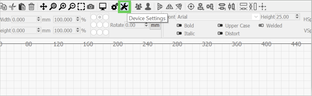
The Device Settings Prompt will open up and you will need to set the following to Green under the Z Control section
-Enable Z Axis
-Relative Z moves only
-Optimize Z moves

Step 3: Do a Coarse Ramp Test
Lets go back to the laser machine. and perform Autofocus to the surface of your material, the lens will be a little closer now that the Focus Distance is set to 0.00mm in the machine settings.
Here is how:
First, jog your laser head using the Laser control screen buttons so that the red dot pointer is over the top of your material.

Like so:

Then press the AF button on the touch screen.
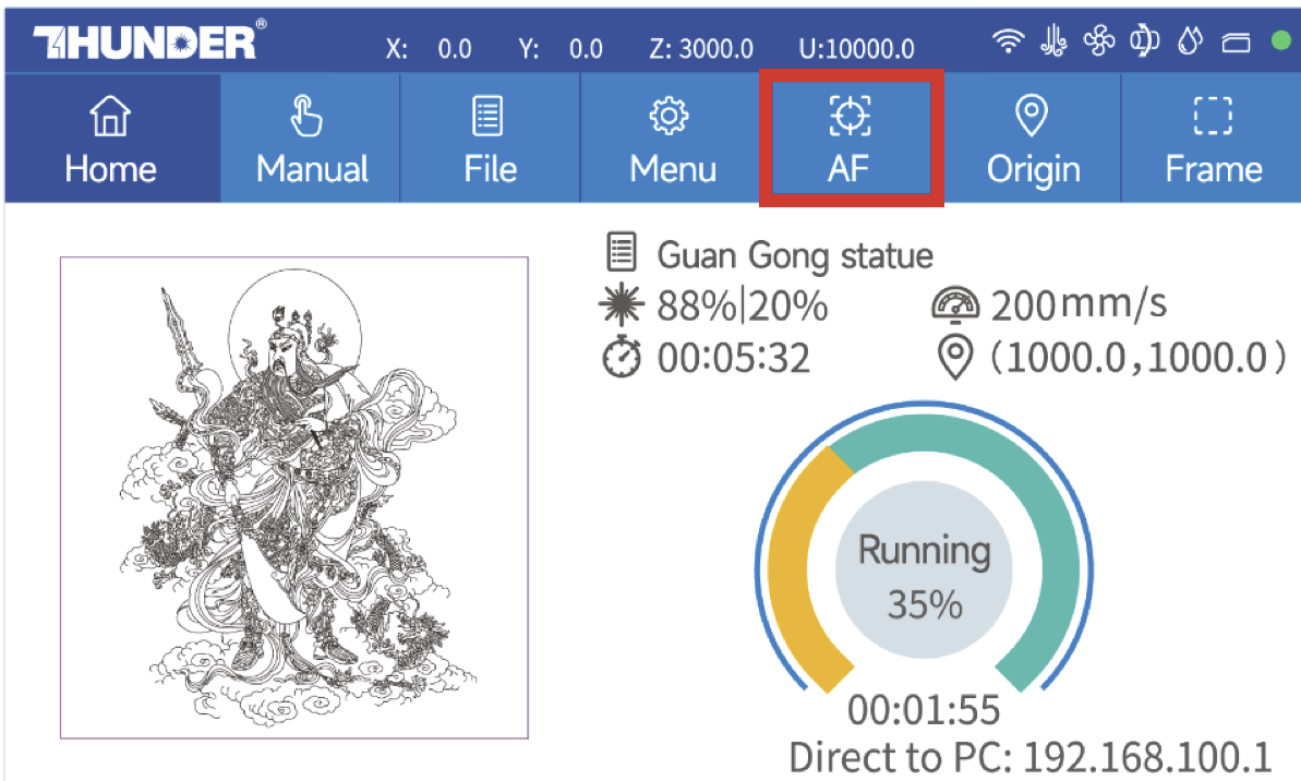
Then click OK on the screen prompt to do the Auto Focus. The machine will raise the material to the Auto Focus position with a 0.00mm offset.

Then, back at your computer, set Lightburn to "User Origin" with the "Top Left radio button" selected as the assigned relative location.

Open the Focus Test Tool in Lightburn from the Laser Tools menu

Configure the test as shown below:

Preview the test:

Next we will focus on setting up the machine origin and framing it to make sure it fits on the selected material:
Jog the Laser Head to your material
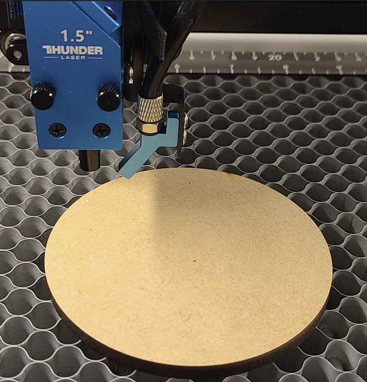
Then set the User Origin using the Origin button on the Laser Touch screen.

Frame the Focus Tool Job from the Focus Tool Prompt in Lightburn and verify that the Frame is on your material

Start the Focus Tool job using the Start button in the Lightburn Focus Tool Prompt:
Before you start the job, be prepared to watch the Z Honeycomb bed move and understand that it is normal If the laser looks like it may crash, be ready on the Estop button.

Observe the results. The Finest line value will be used for the next step for the Fine Ramp Test.

In this example, the 1.6 and 1.8 reading look similar and the best, we will use 1.7 as the median value for the next test.
Step 4: Do a Fine Ramp Test
Using 1.7mm for this example as the median value, the test was set up as shown below, with a target range of 1.2mm to 2.2mm and 20 steps still.
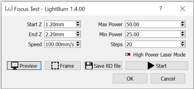

Before you run this Focal Test, be sure to set your new origin (or move the material) and frame the job to verify it is on the material and not overlapping the previous test.
Run the job as before and observe the results
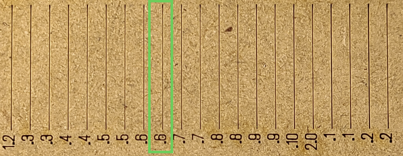
In this case, 1.65mm looks to be the most crisp and will be used as the Focal Distance for the 1.5" lens on this machine.
Step 5: Set the new Focal Distance
In Lightburn, goto Edit>Machine Settings and scroll down to find the Focal Distance setting which should be at 0.00mm. Type in the new value, in this case 1.65mm, and use the "Write" button to send them to the laser machine. Do not close out the "Machine Settings" screen just yet.

Step 6: Backup the new machine settings
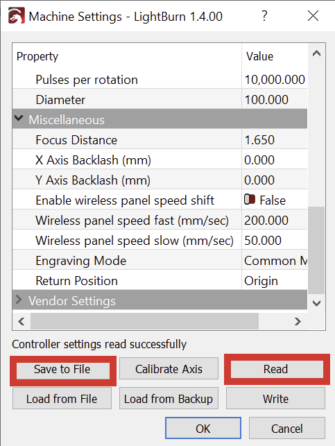
Press the "Read" button and then the "Save to File" Button to save a copy to your computer (add something to the end of the file to differentiate it from the previously saved Original)
Step 7: Disable Z Moves in Lightburn
In Lightburn, select the icon that is a Wrench and Screwdriver, highlighted below.

The Device Settings Prompt will open up and you will need to set the following to Red under the Z Control section
-Enable Z Axis
-Optimize Z moves

Step 8: Do a Sample Engrave Test
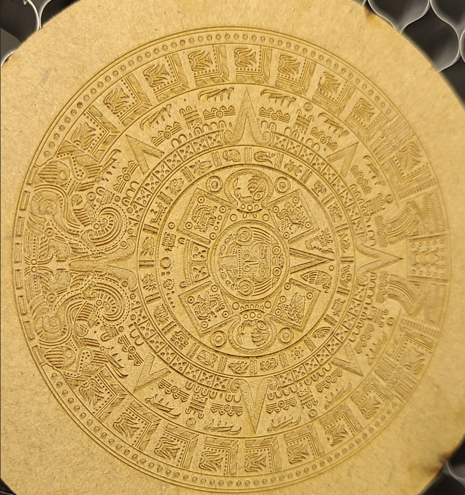
Setup your new material, Auto Focus it and set the User Origin. Run a high detail engrave and observe the results. An example is attached to this article, you may need to adjust based on your material.
Step 9: Set up the manual focus tool
Place the material under the laser head and initiate an AutoFocus.

Place the manual Focus T Bar on the knurled Knob (Notice how it is a little raised\crooked)

Then use the 1.5mm Allen wrench to loosen the set screw on the Manual Focus Tool Shaft.

Reinstall the Manual Focus Tool and let the shaft rest on the material and then tighten the set screw.

Focal Distance Vs Home Offset:
If you run into the case where Focal Distance would need to be negative, you can adjust the value of Home Offset down and carry that adjustment over to the Focal Distance. The two settings work in conjunction to give the total distance away from the Focus Post. If you remove distance from one, add it to the other and then make your final correction so that Focal Distance is a value greater than or equal to 0.
A picture may better help explain. In this example, the values were 5.0mm for Home Offset and 1.7mm for focal distance for a total of 6.7mm. The values could be split to 3mm for home offset and 3.7 mm for Focal distance. Then, when a ramp test is completed, the new focal distance can be set.

Downloads
Still stuck?
Fastest response times in the industry from our US-based support team.