
ACCUMetal NcStudio V15 Laser Cutting Software Users Manual
LINK TO PDF NCStudio User Manual
1 Main Interface
Through this part, you can quickly know the layout of the main interface for NcStudio V15 Laser Cutting CNC System.
The main interface is as follows:
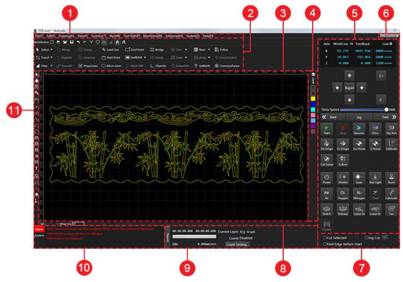
Menu bar
Common toolbar
Drawing window
Layer toolbar
Machine control area
Window display button
Status area
Statistics area
Alarm/system info area
Drawing toolbar
1.1 Common Toolbar
It is used to show the following frequently used instructions:

New: to create a new toolpath file.

Import: to import a DXF / DWG / PLT / G / NC file.

Open: to open a NCEX file.

Save: to save a toolpath file. A new file will be saved as a NCEX file.

Undo: to go back to the previous status.

Redo: to recover canceled operations.
Show order: to show or hide the machining order.

Show direction: to show or hide the machining direction.

Highlight unclosed objects: to mark all unclosed objects with red color.

Clear trace: to clear the machining trace.

Catch: to enable/disable catching function.

Catch options: to open Catch Options dialog box and set options for catching.

Select: to select all objects, deselect selected objects, cancel selected objects, and select unclosed objects, tiny objects, inner objects, outer objects and similar objects. See Select Objects for details.

Transform: to translate objects, rotate objects, vertically or horizontally mirror objects. See Translate Objects, Rotate an Object and Mirror Objects for details.

Clear: to clear some set technics. See Do Clearing for details.

Merge: to open Combine dialog box and combine objects. See Merge Objects for details.

Explode: to trim the toolpath. See Explode Objects for details.

Smooth curve: to make polylines flat and even. See Smooth Curves for details.

Group objects: to bind several objects as a group. See Group and Ungroup Objects for details.

Ungroup objects: to separate the grouped objects. See Group and Ungroup Objects for details.

Preprocess: to open Instant Pre-process dialog box when several target objects are selected and preprocess objects with one click. See Preprocess with One Click for details.

Lead line: to open Set dialog box and set a lead line. See Set a Lead Line for details.

Start point: With a lead line: to set the start point of the lead line; with no lead line: to set the current point as the start point.

Micro joint: to open Micro Joint dialog box and set related parameters. See Execute Micro Joint for details.

Cool point: to open Cooling Point dialog box and add cooling points. See Add Cooling Points for details.

Unfill / fill: to set fill or unfill. See Set Fill or Unfill for details.

Mach direction: to open Set Machining Direction dialog box and set machining direction. See Change the Machining Direction for details.

Bridge: to open Bridge dialog box and bridge objects. See Bridge Objects for details.

Compensate: to open Kerf Compensation dialog box and compensate the kerf. See Set Kerf Compensation for details.

Chamfer: to open Chamfer dialog box and add a chamfer. See Add a Chamfer.

Sort machining order: to set the machining order. See Change the Machining Order for details.

Scan cut: to replan the toolpath to find the most efficient path for machining, so as to avoid unnecessary tool lifting and feeding and improve machining efficiency. See Set Scan Cutting for details.

Instant setting: to set fill/unfill, lead lines, machining direction, machining order and kerf compensation with one click. See Execute Instant Setting for details.

Nest: to do nesting. See Nest for details.

Array: to execute array. See Execute Array for details.

Set berth: to open Set Berth Point dialog box. See Set the Workpiece Origin for details.

Follow: to open Follow dialog box. See Calibrate Capacitance for details.

Control focus: to open Focus Control dialog box. See Control the Focus for details.

Common Param: to open Common Param dialog box, set frequently used parameters, including machine parameters, gas parameters, burst parameters, following-up parameters, scouring parameters, set user habits and switch units. See Common Parameters for details.
1.2 Drawing Window
You can draw and preview objects in this window.
1.3 Layer Toolbar
You can do the following operations related to layer:

: to open Layer dialog box. See Layer Interface for details.
: the selected object(s) is/are included during machining.
: the selected object(s) is/are excluded during machining. At this time, the object(s) turn(s) to white.

: to convert the color of the selected objects into the color of the selected layer.
1.4 Window Display Button
You can show/hide the machine control area by clicking CNC Control in the upper right corner.
1.5 Machine Control Area
It includes the following:
Axis coordinate display area
Manual control area
Machining control area
Machining selection area
1.5.1 Axis Coordinate Display Area
It is shown as follows:
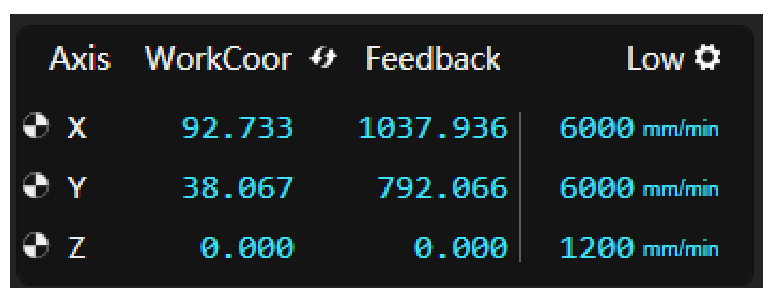
After returning to the machine origin, sign

appears in front of each axis.
In this area, you can do the following:
To switch between workpiece coordinates and machine coordinates, click

.
To separately set low speed, rapid speed and step size for X/Y-axis and Z-axis, click

, and set them in Manual Speed Setting dialog box:
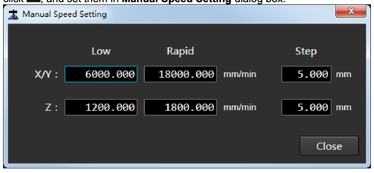
1.5.2 Manual Control Area
It is shown as follows:
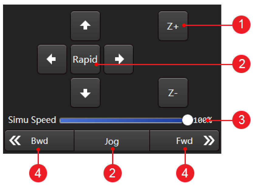
Axis direction buttons: to move each axis towards positive or negative direction.
Feed mode buttons
Jog mode: the default mode.
In this mode, click and hold an axis direction button or several axis direction buttons. The clicked axis/axes move(s) at jog speed until you release the button(s).
To switch back to this mode after switching to Step mode, click Step.Rapid Jog mode: to switch to Rapid jog mode, in Jog Mode, click Rapid. The button is highlighted.
In this mode, click and hold an axis direction button or several axis direction buttons. The clicked axis/axes move(s) at rapid jog speed until you release the button(s).Step mode: to switch to Step mode, click Step.
Click an axis direction button. The clicked axis moves the customized step size.
The default customized step size is 5mm. And you can customize the step size in axis coordinate display area.
Note: Please do not click an axis direction button too frequently because the system needs a certain time to respond.
Simulation speed: to adjust the simulation speed, select one of the following:
Drag the slider.
Click the slider and press PgUp / PgDn or ↑ / ↓ / ← / → on the keyboard.
Movement control button: to control the machine tool to move backwards (Bwd button) / move forwards (Fwd button) along the toolpath:
In jog mode, click and hold the button. The machine tool keeps moving until you release it.
In Step mode, click the button. The machine tool only moves the set step size.
1.5.3 Machining Control Area
It includes the following:

: to start machining from the beginning.
: to stop machining.

: to resume machining from the exact interrupted position when the power interruption or E-stop occurs and the workpiece origin is secured.
: to execute simulation to check the toolpath in real-time.
: to run the machine tool without turning on related ports of laser and machining. There is no actual machining.

: to control the cutting head to return to the workpiece origin.
: to set the workpiece origin.

: to return all axes to the machine origin.

: to return Z-axis to the machine origin.
: to set a follow-up height.

: to turn on the power of the laser device before machining.
: to manually turn on laser shutter.
To eject laser light, first, turn on the laser shutter; then, turn on the laser.
: to turn on/off the laser.
It is automatically turned on when machining starts.
: to manually turn on the red light.
It is used as a kind of guide light to guide the laser position on the sheet.

: to turn on the laser for a certain time.
It keeps on for the set burst time until it is turned off automatically.

: When machining starts, the button will be highlighted, and the system will automatically turn on the blowing valve and blow air.
: When machining starts, the button will be highlighted, and the system will automatically turn on the blowing valve and blow oxygen.
: When machining starts, the button will be highlighted, and the system will automatically turn on the blowing valve and blow nitrogen.

: to set automatic nozzle cleaning. See Set Nozzle Cleaning for details.

: to turn on lube.

: to automatically exchange the workbench, so as to improve machining efficiency.

: to release the workbench during manually exchanging the workbench.

: to control the upper workbench entering the machining area, so as to improve machining efficiency.
: to control the lower workbench entering the machining area, so as to improve machining efficiency.
: to turn on the fan.
Through system parameters Fan On at Machining Start and Fan Off at Machining End to control whether to automatically turn on the fan when machining starts and turn off fan when machining ends.
1.5.4 Machining Selection Area
You can check the following in the area:
Cut Selected: with it checked, the system will only execute machining, dry run, simulation, cutting frame and breakpoint resume for the selected objects.
Jog Cut: with it checked, the laser will keep on during manually moving the axis for a certain distance. After jog cutting ends, the checking status will be canceled by default, and the laser will not be automatically turned on during the next machining.
Find Edge before Start: with it checked, the system will automatically find edges of the sheet before machining.
1.6 Status Area
It is shown as follows:

You can check the following in the area:
Related information of the current drawing objects, including drawing steps and meanings, step results, etc.
Tips during machining.
1.7 Statistics Area
It is shown as follows:

You can do the following in the area:
Open Statistic Information dialog box by clicking Report. See Check Statistics for details.
Open Count Setting dialog box by clicking Count Setting. See Count Machining for details.
1.8 Alarm/System Info Area
It is shown as follows:

You can do the following in the area:
Open Log dialog box by double clicking Alarm / System. See Check System Logs for details.
Troubleshoot the alarm or check the log details by double clicking the related alarm items or system information items.
1.9 Drawing Toolbar
You can do the following in the toolbar:
Draw objects
Execute auxiliary editing
Execute basic editing
2 Quick Start
2.1 Overview
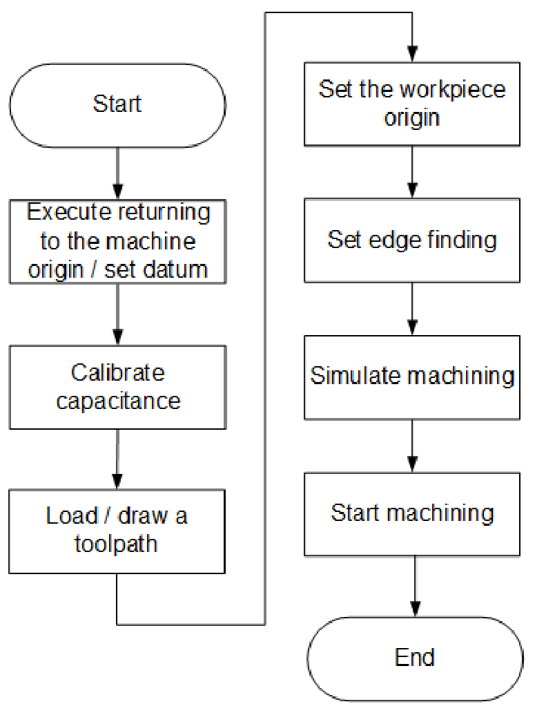
Through this part, you can quickly know the basic machining process of NcStudio-V15 Laser Cutting CNC Control System and start machining sheets.
The process is as follows:
2.2 Execute Returning to the Machine Origin or Set Datum
This operation differs in the encoder type:
Incremental encoder: execute returning to the machine origin
Absolute encoder: set datum
You can set parameter Encoder Type in System Parameters dialog box.
2.2.1 Execute Returning to the Machine Origin
The origin of the machine coordinate system (inherent coordinate system of a machine tool), also called mechanical origin or home, is a fixed point assigned by designing, manufacturing and debugging before the machine tool leaves the factory.
It is used to adjust the machine coordinate of the machine tool, so as to make sure the machining position is correct.
Before executing returning to the machine origin, make sure all servo alarms have been removed.
To execute returning to the machine origin, do the following:
In the menu bar, click Machining → Go Home → Go Home Setting. Go Homing dialog box pops up:
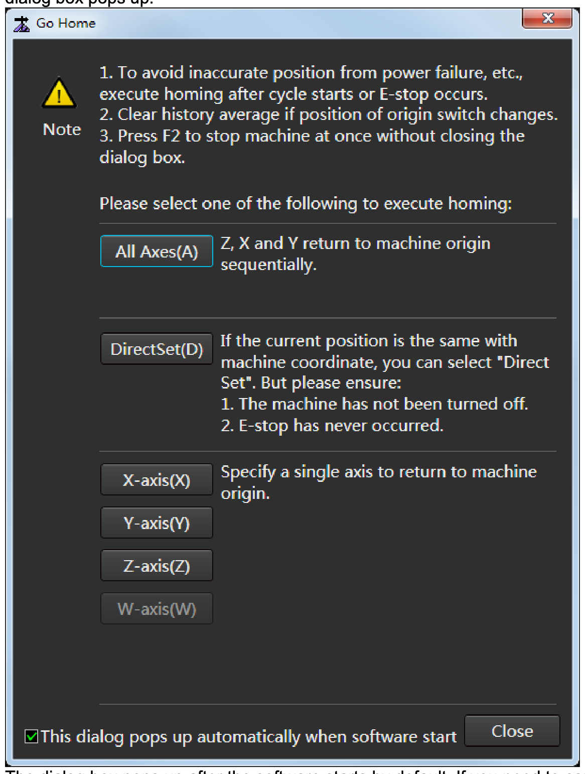
The dialog box pops up after the software starts by default. If you need to cancel the setting, uncheck This dialog pops up automatically when software starts in the bottom.
Click one of the following:
To return all axes to the machine origin, click All Axes. Z-axis returns to the machine origin firstly, then X-axis, Y-axis and W-axis return in sequence.

Alternatively, click in the machine control area.
To return a single axis to the machine origin, click the button for a single axis, the target axis returns to the machine origin.
To return Z-axis, alternatively, click in the machine control area.
If you make sure that the current position is the same with the machine coordinate, the machine tool has never been turned off, and E-stop has never occurred, to set the current position as the machine origin, click DirectSet. Alternatively, in the menu bar, click Machining → Go Home and select a method to return to the machine origin.
After executing returning to the machine origin, sign appears in front of each axis in the machine control area.
2.2.2 Set Datum
With an absolute encoder, you can set the current position of the cutting head as the machine origin through setting datum when you use the system at the first time.
Compared to returning to the machine origin with an incremental encoder, it owns the following advantages:
No need to set returning orders for all axes.
No need to set datum again after restarting the system, and recovering from power interruption and E-stop because the system will automatically read the datum information.
Note: Please set datum again after replacing battery of the absolute encoder.
To set datum, do the following:
In the menu bar, click Machining → Set Datum.
Click one of the following:
To set datum for all axes, click All.
To set datum for the target axis, click the target button.
You can select All(Cancel) to cancel datum setting.
After setting datum, sign appears in front of each axis in the machine control area. And after starting the software or releasing E-stop, the system automatically updates the machine coordinate and feedback coordinate according to feedback pulses to make the current machine coordinate match with the actual coordinate.
2.3 Calibrate Capacitance
It is used to check the corresponding relationship of capacitance and position between the cutting head and the workpiece, so as to move Z-axis up and down in real time and make sure the relative distance between the cutting head and the workpiece is unchanged.
To calibrate capacitance, do the following:
To open Follow dialog box, do one of the following:

In the common toolbar, click Follow.
In the menu bar, click Advanced → Follow Control.
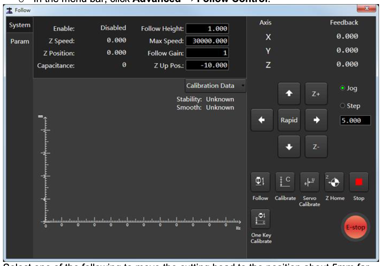
Select one of the following to move the cutting head to the position about 5mm far from the workpiece surface, and keep the workpiece still all the time:
If you have never calibrated capacitance, click the axis direction button.
If you have calibrated capacitance before, click One Key Calibrate.
To eliminate zero drift caused by velocity loop controlling, click Servo Calibrate. The cutting head slightly moves back and forth to compensate the error caused by zero drift.

Click Calibrate.

The system starts to calibrate capacitance for 20s.
2.4 Load or Draw a Toolpath
Before machining, you need to load a prepared toolpath or draw a toolpath in the drawing area.
To load or draw a toolpath, do one of the following:
To load a toolpath, do one of the following:
Drag the target toolpath (supported formats: NCEX / DXF / DWG / PLT / G / NC) into the drawing window.
To load a NCEX file only, select one of the following:
In the common toolbar, click .

In the menu bar, click File → Open.
To import a DXF / DWG / PLT / G / NC file, select one of the following:
In the common toolbar, click .

In the menu bar, to import a DXF / DWG file, click File → Import Dxf/Dwg File.
In the menu bar, to import a PLT file, click File → Import Plt File.
In the menu bar, to import a G / NC file, click File → Import G File, and select one of the following:
Import Standard G File: before importing such a file, please modify the file and make its format meet our requirement. After importing such a file, to adjust or switch the view, right click on the drawing window.
Import CAD Info in G File: to only import CAD information in the G file.
Note: The file loaded by Import command will be automatically saved as a NCEX file.
To draw a toolpath, do one of the following:
Manually draw a toolpath in the drawing window.
To call an object saved in the gallery, click Gallery in the drawing bar or click Drawing → Gallery in the menu bar, select the target object in Gallery dialog box, set the related parameters. The object adds into the drawing window.

To insert another NCEX / DXF / DWG / PLT / G / NC file without overwriting the original one, in the menu bar, click File → Insert.
After loading or drawing a toolpath, you can do the following:
Edit toolpaths.
Preprocess toolpaths.
Set technics.
Set layer.
After executing the above operations, select one of the following in the menu bar, and save the toolpath as a NCEX file:
To save all objects, select one of the following:
To save all objects in the default path, click in the common toolbar, or click File → Save in the menu bar.

The file will be put in NceFiles folder in the desktop. If such a folder does not exist, the system will automatically create one.
To save all objects in the target path, click File → Save As in the menu bar, and select the target path.
To only save the selected objects and put them into the target path, click File → Save Selected As in the menu bar, and select the target path.
2.5 Set the Workpiece Origin
The zero point of each axis in the toolpath is the workpiece origin. Before machining, you need to define the actual position of the workpiece origin on the sheet.
To set the workpiece origin, do one of the following:
In the drawing window, drag which is at the intersection of the horizontal scale and vertical scale to the target position:
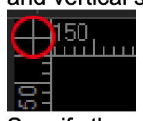
Specify the position of the cutting head as the workpiece origin:
In the machine control area, to move the cutting head to the target position, click / / / .




To set the current position as the workpiece origin, click or press F5.

To specify the coordinate of X-axis / Y-axis as the workpiece origin, in the menu bar, click Machining → Set Work Origin → X-axis / Y-axis. The workpiece coordinate of the current workpiece coordinate system turns to zero.
Set the workpiece origin by mouse:
In the drawing toolbar, click . The cursor turns into .

Left click to specify the workpiece origin.
To exit specifying the workpiece origin, right click.
2.6 Set Edge Finding
It is used to calculate the rotation angle between the current sheet and the machine coordinate system, so as to rotate the workpiece coordinate system (WCS) in the toolpath at the corresponding angle and establish a new WCS.
To set edge finding, do the following:
To open Edge Finding dialog box, click

in the common toolbar or Machining → Edge Finding in the menu bar.
In the lower left, set Enable Edge Finding to ON status.
Select a finding mode:
Auto: Used to specify a new WCS by automatically finding three points according to the set berth point.
Three-point: Used to specify a new WCS by three points.
Two-point: Used to specify a new WCS by two points.
2.6.1 Set Automatic Edge Finding
The origin O' of the new WCS is the berth point. And the direction of edge finding is the adjacent edges that close to the berth point.
The relationship between the berth point and the direction of edge finding is as follows:
Berth Point | X-axis Direction | Y-axis Direction |
|---|---|---|
Lower right | Positive | Negative |
Upper right | Positive | Positive |
Lower left | Negative | Negative |
Upper left | Negative | Positive |
Before setting automatic edge finding, make sure the berth point is at the upper right / lower right / upper left / lower left.
To set automatic edge finding, do the following:
To switch to the page of automatic edge finding, in Finding Mode area of Edge Finding dialog box, click Auto:
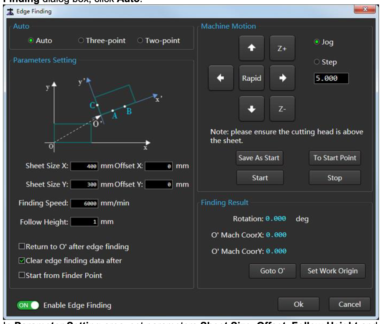
In Parameter Setting area, set parameters Sheet Size, Offset, Follow Height and Finding Speed.
Manually move the cutting head above the sheet.
Optional: If it is the first time for the system to find edges, click Save As Start in Machine Motion area to record the machine coordinate of the start point for edge finding.
With Start from Finder Point checked in Parameter Setting area, the system will start to find edges from the recorded start point by default.To start to find edges automatically, click Start. The system judges the long edge and the short edge according to the set value of parameter Sheet Size.
Optional: To return the cutting head to point O' after automatic edge finding, check Return to O' after edge finding.
The system starts to automatically find edges as follows:
Locate point C:
Enable the height sensing unit at the current position.
Move towards the short edge at the set finding speed. The edge point is point C.
Locate point A:
Enable the height sensing unit at the position which is 20% away from the short edge.
Move towards the long edge. The edge point is point A.
Locate point B:
Enable the height sensing unit at an another position which is 20% away from the short edge.
Move towards the long edge. The edge point is point B.
2.6.2 Set Edge Finding by Three-point
Before setting edge finding by three-point, in the machine control area, click

to guide the position.
To set edge finding by three-point, do the following:
To switch to the page of three-point, in Finding Mode area of Edge Finding dialog box, click Three-point:
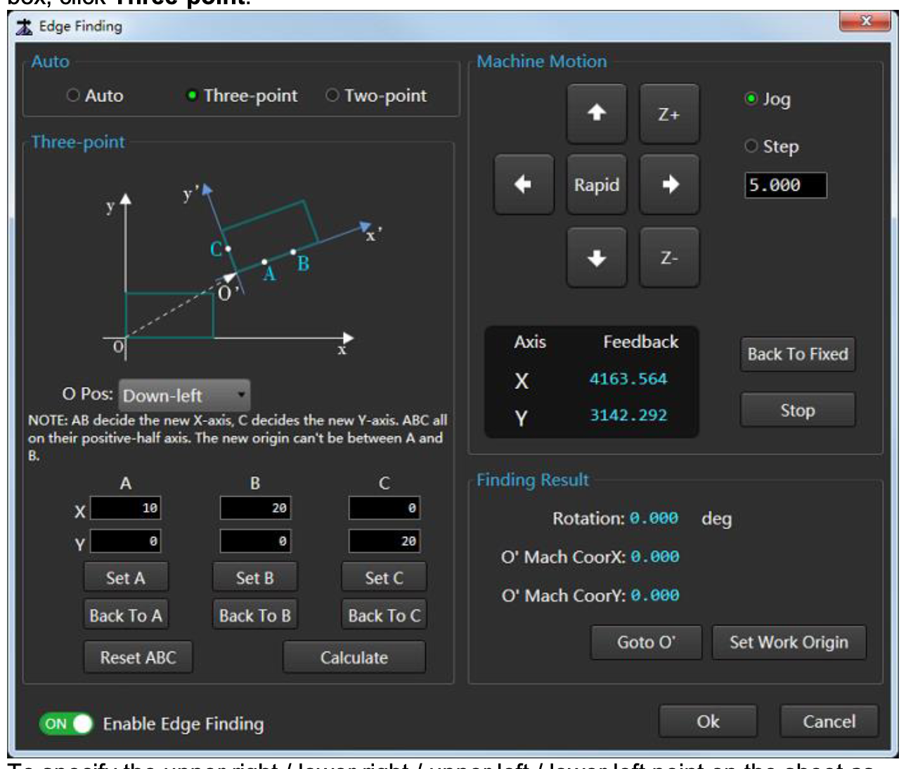
To specify the upper right / lower right / upper left / lower left point on the sheet as the origin O' of the new WCS, select a point in the drop-down box of O Pos. The corresponding diagram shows in Three-point area.
To confirm the new WCS by specifying three points A, B and C, do the following:
To specify points A and B, manually move the cutting head to the sheet edge in X-axis positive direction and click Set A and Set B. The system automatically connects points A and B to specify a new X-axis.
X-axis coordinate of point A should be smaller than that of point B.To specify point C, manually move the cutting head to the sheet edge in Y-axis positive direction and click Set C.
The system automatically specifies a new Y-axis by taking a perpendicular line to line AB through point C and confirms a new WCS.
Optional: To restore the current coordinate to the default value, click Reset ABC.
To check the calculated locating result in Finding Result area, click Calculate in Three-point area.
If the rotation angle exceeds 15°, it indicates that the sheet is tilted. At this time, please place the sheet and do edge finding again.
2.6.3 Set Edge Finding by Two-point
Before setting edge finding by two-point, in the machine control area, click

to guide the position.
To set edge finding by two-point, do the following:
To switch to the page of two-point, in Finding Mode area of Edge Finding dialog box, click Two-point:
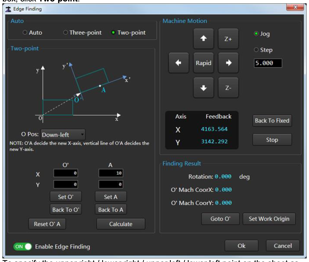
To specify the upper right / lower right / upper left / lower left point on the sheet as the origin O' of the new WCS, select a point in the drop-down box of O Pos. The corresponding diagram shows in Two-point area.
To define the new WCS by specifying point A, manually move the cutting head to the sheet edge in the positive direction of X-axis and click Set A. The system automatically connects points A and O’ to specify a new X-axis, and constructs a perpendicular line to line O'A through point O' to specify a new Y-axis.
Optional: To restore the current coordinate to the default value, click Reset O'A.
To check the calculated locating result in Finding Result area, click Calculate in Two-point area.
If the rotation angle exceeds 15°, it indicates that the sheet is tilted. At this time, please place the sheet and do edge finding again.
2.7 Simulate Machining
It is used to see the moving track of the machine tool before actual machining, so as to avoid damage to the machine tool due to programming mistakes in the toolpath file.
It includes the following:
Simulation: to check the toolpath in real time without running the machine tool. It provides a fast but lifelike simulation machining environment. During simulation, no actual machining occurs, and only the moving track of the cutting head at high speed shows in the drawing window.
Frame cutting: to confirm the machining range by running the system along the frame of the toolpath. During frame cutting, no actual machining occurs.
Dry run: to move the machine tool without turning on the laser and related ports of laser. During dry run, no actual machining occurs.
To simulate machining, do one of the following:
Simulation
Note: Before simulation, make sure the toolpath file has been saved and the system is in idle status.
In the machine control area, click .
In the menu bar, click Machining → Mach Control → Simu.
On the keyboard, press F8.
The machine tool starts simulation from the beginning of the toolpath file.
Frame cutting
In the machine control area, click .
In the menu bar, click Machining → Mach Control → Cut Frame.
Dry run
In the machine control area, click .
In the menu bar, click Machining → Mach Control → Dry Run.
2.8 Start Machining
It is used to automatically execute toolpath file until the end of block or any intentional interruption.
Before starting machining, make sure the following:
The toolpath file has been saved.
No E-stop and alarms occur.
To start machining, do one of the following:

In the machine control area, click .
In the menu bar, click Machining → Mach Control → Start.
The system starts machining from the beginning of the toolpath file.
During machining, you can do the following:
To stop machining, do one of the following:
In the machine control area, click .
In the menu bar, click Machining → Mach Control → Stop.
Machining stops and the system enters idle status.
To execute breakpoint resume when the power interruption or E-stop occurs and the workpiece origin is secured, do one of the following:
Note: Before executing breakpoint resume, please make sure the machine coordinate is correct. Otherwise, please execute returning to the machine origin first.
In the machine control area, click .
In the menu bar, click Machining → Mach Control → Resume.
3 Object Operations
3.1 Drawing
This part introduces the drawing tools that are used to draw objects in the drawing window for machining.
To select a drawing tool, do one of the following:
In the menu bar, click Drawing and select a drawing tool.
In the drawing toolbar, select a drawing tool:

: Dot

: Polyline

: Line

: Elliptic arc

: Arc

: Ellipse

: Circle

: Polygon

: Star

: Rectangle

: Text
After drawing, do the following:
To exit drawing, right click or press Esc.
To adjust the object, select the target object and do one of the following:
In the common toolbar, to modify the size and position of the object, directly input the values.
In the drawing window, to modify the size of the object, drag the rectangular points around the object.
3.1.1 Draw a Polyline
A polyline is a chain of lines and arcs that are joined together into one object. It includes line and tangent arc. The tangent arc corresponds to the arc.
To draw a polyline, do the following:
Click .

Left click to specify two points to draw a line.
Optional: To switch to the arc mode, right click on the drawing window and select Tangent Arc.
The arc is tangent to the last line/arc.
If you need to switch back to the line mode, right click on the drawing window and select Line.Left click to specify another point.
Right click and do one of the following:
To draw the end point of the polyline, select Confirm. The polyline is an unclosed object.
To connect the current point to the start point, click Close. The polyline is a closed object.
To cancel the previous operations and exit drawing a polyline, click Cancel.
After drawing a polyline, to change an unclosed polyline into a closed one, select it and check Close in the common toolbar. (Note: This operation is irreversible.)
3.1.2 Draw an Elliptic Arc
To draw an elliptic arc, do the following:
Click .

Draw an ellipse.
Refer to Draw an Ellipse for details.Left click to separately specify the start point and the end point.
3.1.3 Draw an Arc
To draw an arc, do the following:
Click .

Left click to specify the center point.
Left click to specify the start point.
The distance between the start point and the center point is the radius.Left click to specify the end point.
3.1.4 Draw an Ellipse
To draw an ellipse, do the following:
Click .

Left click to specify the center point.
Left click to separately specify two points.
The distances between the center point and the two points are separately the major axis and minor axis of the ellipse.
3.1.5 Draw a Circle
To draw a circle, do the following:
Click .

Left click to specify the center point.
Left click to specify a point.
The distance between this point and the center point is the radius.
3.1.6 Draw a Polygon
To draw a polygon, do the following:
Click .

Set parameter Edges in the common toolbar and press Enter on the keyboard.
Left click twice to separately specify the center point and a vertex.
3.1.7 Draw a Star
To draw a star, do the following:
Click .

Set parameter Vertexes in the common toolbar and press Enter on the keyboard.
Left click twice to separately specify the center point and a vertex.
3.1.8 Enter Text
It is mainly used to draw text in an advertisement board.
To enter text, do the following:
Click .

To specify a text box, click and drag the mouse.
Enter text in the input box.
During this process, you can press Ctrl + Enter for line feed.Press Enter.
3.2 Auxiliary Editing
You can do the following for better effects of object editing:
View objects
Set catch options
Select objects
Measure distance
Check the objects
Switch to the fill mode
3.2.1 View Objects
It is used for a better view of objects without changing the actual sizes and coordinates.
It includes the following:
Pan the view
Zoom in/out the view
Zoom in the selected area
Fit to window
3.2.1.1 Pan the View
It is used to reposition the drawing window by selecting a base point and a second point for the new position.
To pan the view, do one of the following:
Press the mouse wheel and drag the mouse at the same time to move the view to the target position.
Do one of the following to call Pan command, and hold the left mouse button to move the view to the target position:
In the drawing toolbar, click

.
In the menu bar, click View → Pan.
To stop panning the view, right click or press Esc.
3.2.1.2 Zoom in/out the View
It is used to zoom in or zoom out the view. Through changing the size of the shown area and objects, you can draw objects more precisely
To zoom in/out the view, do the following:
To call Zoom command, in the menu bar, click View → Zoom.
Do one of the following:
Scroll up the mouse wheel to zoom in the view and scroll down the mouse wheel to zoom out the view.
Hold and drag up the left mouse button to zoom in the view, and hold and drag down the left mouse button to zoom out the view.
On the numeric keypad, press + to zoom in the view, and press - to zoom out the view.
To stop Zoom command, right click or press Esc.
3.2.1.3 Zoom in the Selected Area
It is used to zoom in the selected part of the object to the size of the drawing window.
To zoom in the selected area, do the following:
To call Zoom by Rect command, do one of the following:
In the drawing toolbar, click

.
In the menu bar, click View → Zoom by Rect.
Left click on the drawing window, drag the mouse to form a rectangle and left click again. The area formed by the rectangle zooms in.
3.2.1.4 Fit to Window
It is used to resize objects and make them fit to the drawing window on the premise of showing all objects.
To fit to window, do one of the following:
In the drawing toolbar, click

.
In the menu bar, click View → Best View.
On the numeric keypad, press *.
3.2.2 Set Catch Options
It is used to precisely locate feature points and connect objects during drawing an object.
Once the cursor moves close to the feature points, the system can easily locate to the points.
To set catch options, do the following:
To open Catch Option dialog box, do one of the following:
In the common toolbar, click

.
In the menu bar, click Drawing → Catch Options.
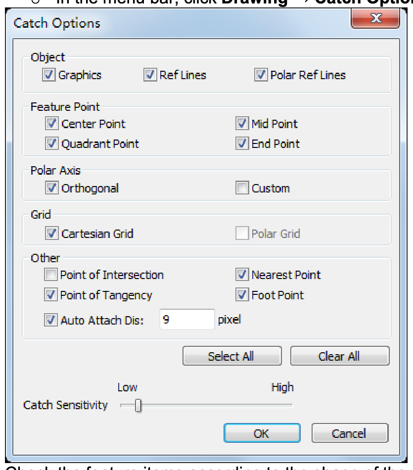
Check the feature items according to the shape of the object.
Adjust the catch sensitivity.
It is easier to get the feature points with higher catch sensitivity.Optional: If Custom is checked in Polar Axis area, to set the incremental angle, do the following:
In the menu bar, click Drawing → Polar IncAngle. Polar Axis Inc. Angle dialog box pops up.
Check Enable and set the incremental angle.
The system catches feature points based on the set incremental angle.
When the system rotates the set angle, a polar axis line appears.To enable catching function, do one of the following:
In the common toolbar, click

.
In the menu bar, click Drawing → Catch.
3.2.3 Select Objects
It is used to select objects for editing.
To select objects, do one of the following:
Freely and manually select any objects.
Automatically select objects based on the same standard.
3.2.3.1 Manually Select Objects
To manually select objects, do the following:
In the drawing toolbar, to call Select graph command, click

.
Do one of the following:
To select a single object, left click the target object on the drawing window.
To select several objects, press Ctrl and left click the target objects one by one.
To select objects contained in the selected area, hold the left mouse button to drag from upper left to lower right.
Objects intersected with the area will not be selected.To select objects intersected with or contained in the selected area, hold the left mouse button to drag from lower right to upper left.
3.2.3.2 Automatically Select Objects
To automatically select objects, do one of the following:
Click

Select in the common toolbar, or click Edit → Select in the menu bar, and select one of the following in the drop-down box:
Select Unclosed: to automatically select all unclosed objects.
Select Tiny: to automatically select all objects within the target size.
Select Similar: to select all the similar objects after selecting one object, ignoring the difference of angle.
Select Similar: to select all the similar objects after selecting one object, paying attention to the difference of angle.
In the menu bar, click Edit, and select one of the following:
Select by Layer: to automatically select all objects within the same layer.
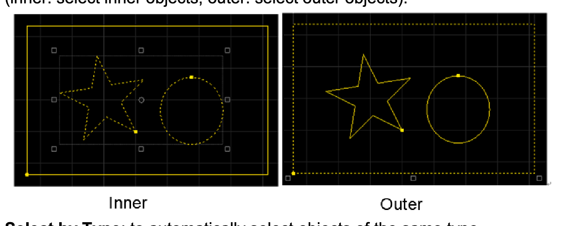
Select by Inner-Outer: to automatically select objects based on the nesting (inner: select inner objects; outer: select outer objects):
Select by Type: to automatically select objects of the same type.
3.2.4 Measure Distance
It is used to measure distance, X-axis / Y-axis offset and the vector angle between two points.
To measure distance, do the following:
To call Measure command, do one of the following:
In the drawing toolbar, click

.
In the menu bar, click View → Measure.
Left click to select the start point for measuring, and move the cursor to select the end point.
The measurement result shows near the end point.
3.2.5 Check the Objects
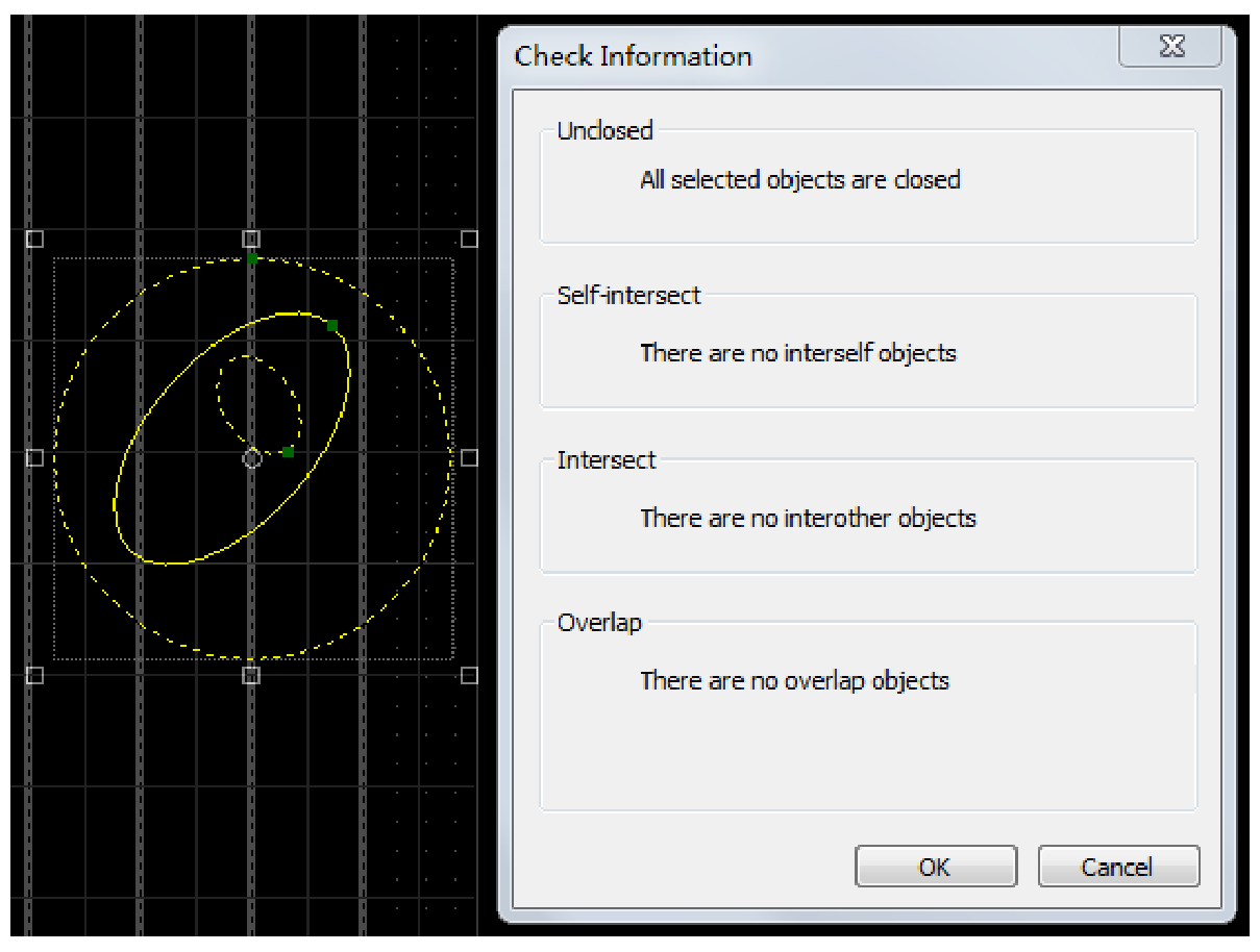
It is used to examine the imported or drawn objects to see if there exist unclosed / self-intersected / intersected / overlapped objects.
To check the objects, do the following:
In the menu bar, click View → Graphic Detection. Shape Check dialog box pops up:
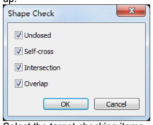
Select the target checking items.
After checking the objects, Check Information dialog box pops up:
3.2.6 Switch to the Fill Mode
It is used to view closed objects that are set as Fill. In the fill mode, objects set as Fill are filled in while and others are shown in the wireframe.
All objects are shown in the wireframe by default.
To switch to the fill mode, in the menu bar, click View → Fill Mode.
To switch to the wireframe mode, in the menu bar, click View → Wireframe Mode.
3.3 Basic Editing
It is used to edit drawn and imported objects, so as to modify the toolpath according to the requirement.
It includes the following:
Translate objects
Rotate an object
Mirror an object
Align objects
Scale objects
Merge objects
Share an edge
Group objects
Ungroup objects
Explode objects
Break objects
Execute array
After editing objects, you can click File → Export File to import the target objects as a DXF / DWG file in the menu bar for later use.
3.3.1 Translate Objects
It is used to move objects a certain distance. As a result, the coordinate of objects will be changed without changing the size of objects.
To translate objects, select the target objects, and do the following:
Press the left mouse button and drag the objects.
On the keyboard, press ↑ / ↓ / ← / →.
Call Translate command:
Click

Transf → Translate in the common toolbar, or click Edit → Translate in the menu bar.
Left click on the drawing window.
Move the cursor to the target position and click again.
3.3.2 Rotate an Object
It is used to move or turn an object around a certain fixed point, so as to change the position and direction of the object.
To rotate an object, select the target object, and do one of the following:
Left click to define a point.
The point is the rotation center by default.In the common toolbar, enter the rotation angle in Angle input box and press Enter.
If the object is a rectangle or text, the lower left point of the object is the rotation center.
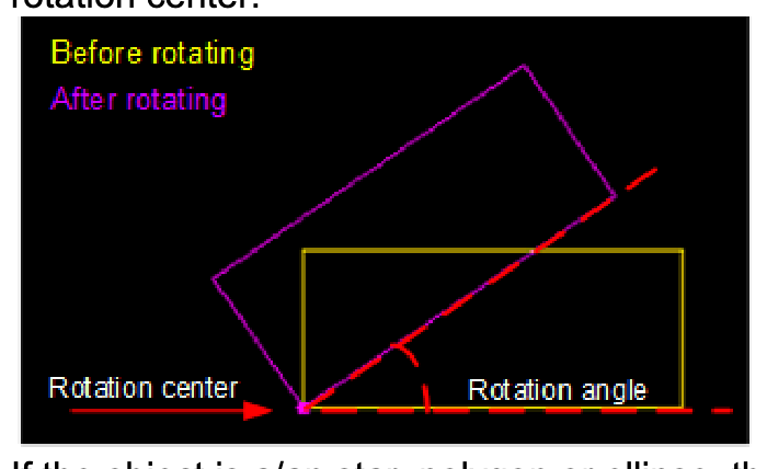
If the object is a/an star, polygon or ellipse, the center point of the object is the rotation center.
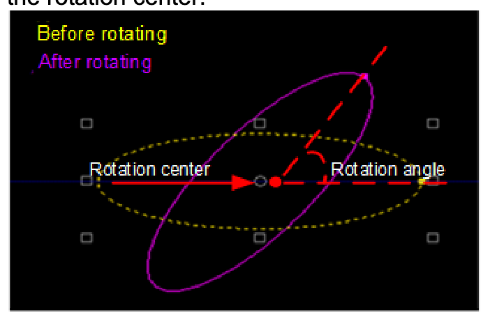
Call Rotate command:
In the common toolbar, click

Transf→ Rotate, or click Edit → Rotate.
Left click to select the rotation center.
Move the cursor to adjust the rotation angle.
Left click to confirm.
3.3.3 Mirror an Object
It includes the following:
Vertical mirror: mirror along X-axis with the center of the object as the center of rotation.
Horizontal mirror: mirror along Y-axis with the center of the object as the center of rotation.
To mirror an object, select an object, and do one of the following:
In the common toolbar, click

Transf → Vertical Mirror / Horizontal Mirror.
In the menu bar, click Edit → Mirror → Vertical Mirror / Horizontal Mirror.
3.3.4 Align Objects
It is used to arrange the objects in a straight line.
To align objects, select several objects and do one of the following:
To align objects by the center point, in the drawing toolbar, click

.
In the menu bar, click Edit → Align, and select one of the following:
Align Left
Align Right
Align Top
Align Bottom
Align Center Point
Align Horizontally
Align Vertically
Distribute Horizontally
Distribute Vertically
The system automatically aligns objects.
3.3.5 Scale Objects
It is used to make objects appear larger/smaller in the equal proportion.
To scale objects, select the target objects, and do the following:
In the common toolbar, enter the scaling factor in Scale input box and press Enter.
In the menu bar, call Scale command:
Click Edit → Scale.
Left click to select the center point for scaling.
Move the cursor to adjust the scaling factor.
Left click to confirm.
3.3.6 Merge Objects
It is used to combine unclosed objects within the set tolerance, so as to help to avoid unnecessary tool lifting and improve machining efficiency.
Tolerance is the allowable distance between objects that need to be combined.
The target objects cannot be the following:
Closed object
Dot
Text
Group
Before merging objects, it is suggested to enable catch options.
To merge objects, select the target objects, and do the following:
To open Join dialog box, do one of the following:
In the common toolbar, click

Merge.
In the menu bar, click Edit → Merge.
Right click on the drawing window and select Merge.
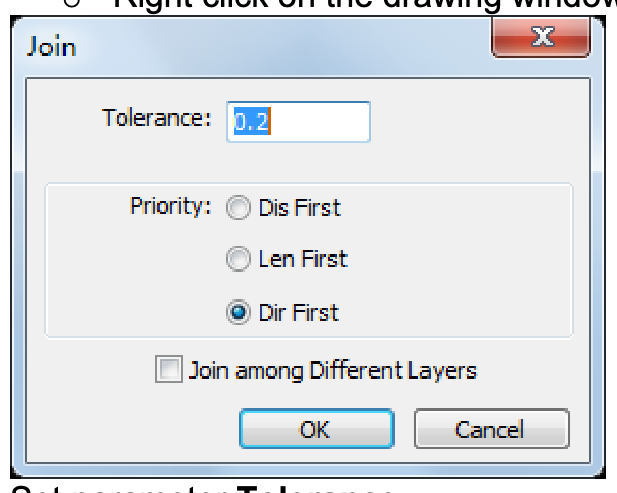
Set parameter Tolerance.
Range: 0.01mm~10mmSelect a priority strategy to decide the standard for combining.
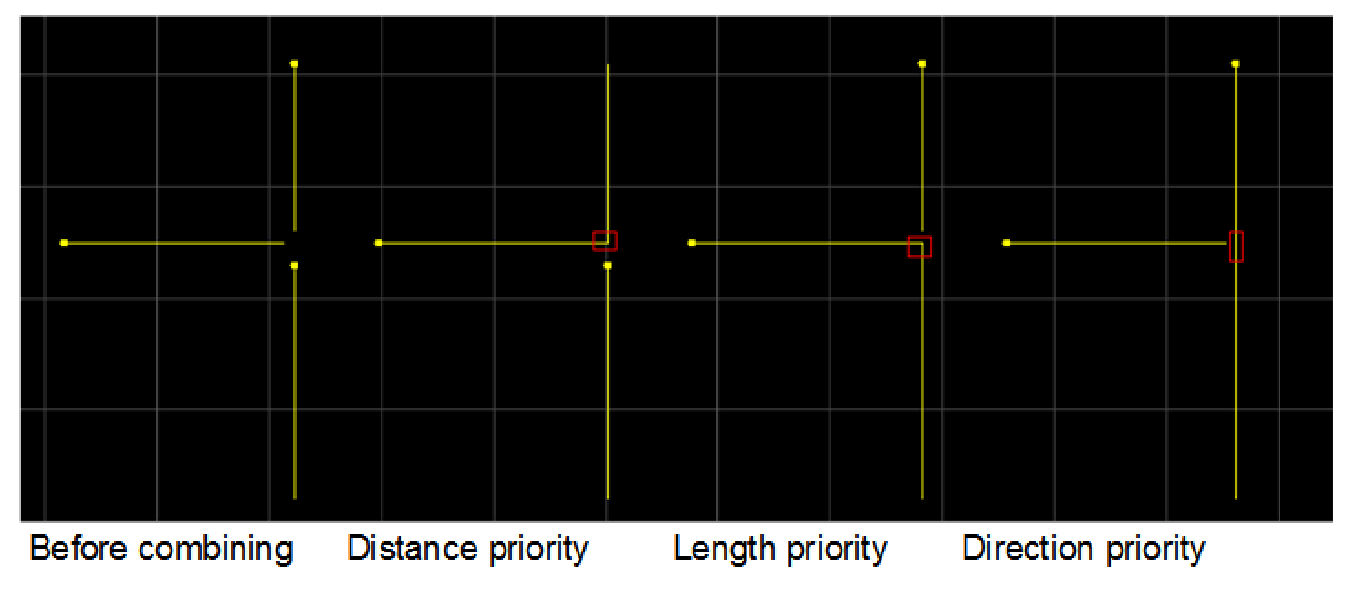
If there exist more than two end points can be combined, the system combines objects that are nearest / longest / in the same direction.Optional: Check Merge among different layers. The system merges objects of different layers into the layer with a higher layer order.
The result is as follows:
3.3.7 Share an Edge
It is used to make the overlapped edges become a shared edge, so as to avoid cutting the same edge during machining, and optimize the toolpath.
The error for sharing an edge is 0.1mm.
Before sharing an edge, make sure the following:
The shared objects are closed objects and share the same point.
The shared edge is a line or an arc.
To share an edge, select at least two objects, do the following:
To open Common Edge dialog box, do one of the following:
In the menu bar, click Planning → Common Edge.
Right click on the drawing window, and click Common Edge.
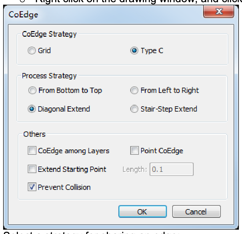
Select a strategy for sharing an edge:
Grind: cut internal objects first.
C Type: cut objects in the shape of character C.
Optional: If the strategy is C Type, select a machining order:
From Bottom to Top: cut objects from bottom to top.
From Left to Right: cut objects from left to right.
Diagonal Extend: cut objects in the lower-left region first and cut its adjacent objects circle. The toolpath is like an ever-widening arc. The marching direction is from the lower-left region to the upper-right region.
Stair-step Extend: it is applicable to rectangular objects. Its toolpath is like stair steps. The extending direction is from the lower-left region to the upper-right region.
Optional: Check the following items in Others area:
Share Edge among Layers: to make objects in the different layers share the edge.
Share Point: to make objects that share the same point as a group.
Extend Starting Point: to extend the toolpath in the opposite machining direction through the start point and turn on the laser in advance, helping completely cut the start point and avoid over-burning.
It is applicable to rectangular objects.Prevent Collision: to avoid colliding with the cutting head after cutting parts in the first region of shared objects.
It is only applicable to strategy C Type. With it checked, the shared edge will be cut in the second region. Otherwise, the shared edge will be cut in the first region.
After sharing an edge, the objects turn into a group.
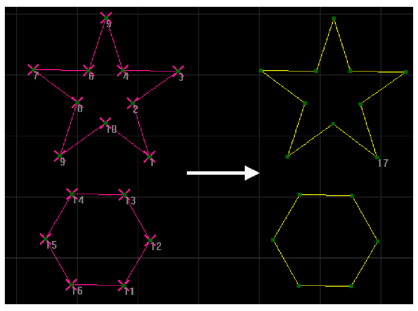
3.3.8 Group Objects
It is used to bind several objects, so as to edit them at the same time.
To group objects, select several objects, and select one of the following:
In the common toolbar, click

Group.
In the drawing window, right click and select Group.
In the menu bar, click Edit → Group/Ungroup → Group.
The result is as follows:
3.3.9 Ungroup Objects
It is used to separate the grouped objects, so as to edit each part of the objects independently.
To ungroup objects, select the target group, and do one of the following:
In the common toolbar, click

Ungroup.
Right click on the drawing window and select Ungroup.
In the menu bar, click Edit → Group/Ungroup → Ungroup.
Still stuck?
Fastest response times in the industry from our US-based support team.