
Preface: This is for the Thunder Aurora 8 Series Galvo Lasers with auto focus.
Quickstart Video
**coming soon**
Complete Guide
The below steps show how to swap and configure your new lens. Yes..it is more than just swapping the lens out in the machine. No, Lightburn does not do all the work. There will be a few steps that you do here that once done, are done. You will then be able to easily swap between calibrated lens.
Pre-requisites
You must install the Thunder Laser Auto Focus Software and successfully connect to the Aurora laser's internal auto focus board. This procedure will vary based on whether you use Mac or Windows. If you have multiple Auroras, it would be good to only have one plugged in via USB for this procedure.
Tools and Materials Needed
- Cardboard or similar material that your Aurora can mark with known good settings
- Aluminum coated business card or similar
- Metric Ruler or Digital Calipers
- Pen
Procedure
0. Prework - Capture Current Lens Focus Position
In this step, you will gather data about your current auto focus set point. It would be good to write this value down so that as you swap between lenses, you will know what the Auto Focus set point was set to previously. To do this, open up the Auto Focus software and connect it to your aurora.
Note: Make sure you select the proper serial channel (Comm port). Due to the nature of how Serial comms work on a computer, the Connection status may say Connected but that is only it being connected to the Registers associated with an active Comm Port on the computer. If nothing on the other end of that comm port is talking or sending data in a way that the Auto Focus Software understands, then the focus values will not update.
| Windows Comm Port Selection | Reading the Value |
|---|---|
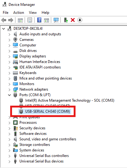
*Note that I could have selected the incorrect comm port 7. The TL Auto Focus software would have connected to the port 7 but no communication would happen successfully |
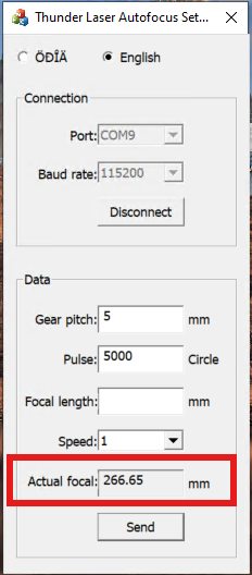
The current lens which is a F-170 in this example has a setpoint of 267. |
So once you are connected properly, simply auto-focus your Aurora and then read the value in the Actual Focal field at the bottom of the prompt. That is your current focus +-1mm or so.
Note: Once you get proficient with the Auto Focus software, you can use the software to set custom focal heights for different tasks very quickly.
1. Physical Lens Swap
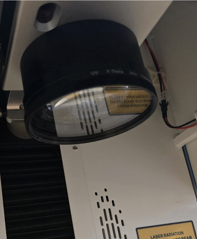
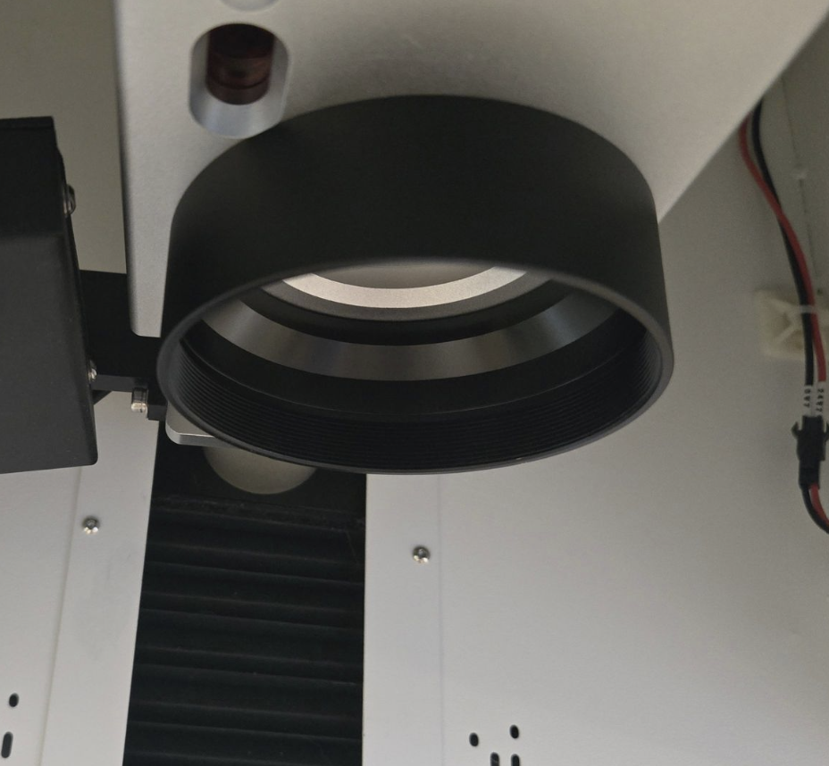
In this step, you will swap the lens. Pay attention to the spacer rings and such on your lens assembly. The Lens should easily thread into place and be snugged up.
Watchouts would be: Leave the spacer rings on the galvo head, only should be replacing the lens part. Put your dust caps back on for storage. This would be a good time to clean and inspect. The threads on the lens are very fine, standard right hand threads. Turning to the right will tighten them.
| Lens Installed | Lens Removed |
|---|---|
 |
 |
2. Lightburn Profile Creation
In this step, you will copy your existing device profile, rename it for the new lens size and use the new profile as the starting point for creating the final settings for the new lens. This will copy over all your current device settings so that your new Device profile operates similarly.
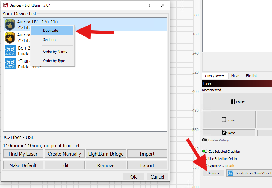
Click the Devices button in Lightburn, then in the Devices window, select the profile for your Aurora that you want to duplicate, then Right Click that profile and select Duplicate.
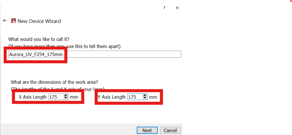
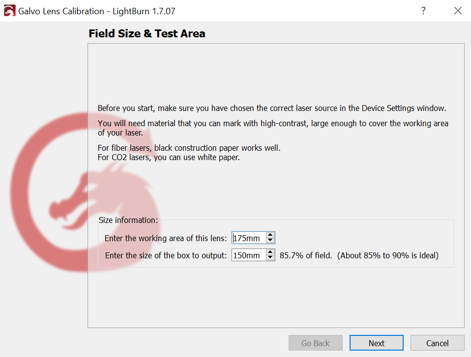
Click the NEXT button to go through the prompts and rename the new profile something meaningful as well as entering the new workspace size (For this lens I chose 175mm, yours will vary. Please refer to the Aurora Manual or articles in the knowledge base for further information). Click Next and then Finish
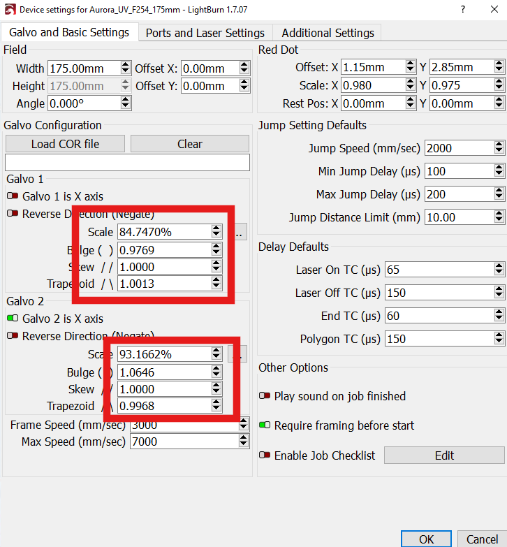
We will need to remove the calibration/cor file settings prior to starting any additional calibration steps for the newly created device profile as those settings are applicable to the other lens that we duplicated the device profile from. To do this, complete the following steps:
Select the proper device:
Note: Lightburn may have swapped off your original device or switched to another. Be sure to select your NEW device profile.
Start by making sure your newly created device is selected in the dropdown menu in the Laser window. Then in Device Settings (edit>Device Settings or the Screwdriver/Wrench icon shown below), set scale to 100 and bulge/skew/trapezoid all to 1 on the Galvo and Basic Settings tab.
| Before | After |
|---|---|
 |
 |
3. Dialing in the Focal Height
In this step, you will be using the nominal focal height from the manual for the selected lens. You will be burning some test lines to find the optimal focal height. You will need some test material to mark and some known decent settings to mark the material. Once you find the optimal height, that value will be used are your optimal focus for this lens.
For this tutorial we are going from a F-170 Lens to a F-254 Lens. The snippet from the Aurora Manual shows that the physical distance from the lens to the material to be xxxmm and for the F254 lens it should be xxxmm. Now...the value we read earlier in the prework showed a Focus Sensor value (won't be the same as Lens Focus value since the sensor sits higher) to be 267mm. To get a starting point, we will take the 267mm value, subtract the F170 Focal lens value of xxxmm and then add that value to the F254mm focus value of xxxmm to get a starting point for the F254 Focus Sensor value of xxxmm.
Summary Table:
| F-170 | F-254 | |
|---|---|---|
| Focal Lens Height | ||
| Focus Sensor Height | ||
| Delta Sensor-Lens |
Enter the calculated Focus Sensor Height Value for the new lens into the Auto Focus Software and click Send. Look for the "Send Successful!" message.
Similar to a ramp test on a gantry CO2, we need to find where the beam marks the best with the smallest beam spot/thinnest line. This can be done a few ways.
4. Setting the Auto Focus Focal Height Value
In this step, you will be taking the value from the previous step and inputting it into the Auto Focus Software to save as the set point for your lens.
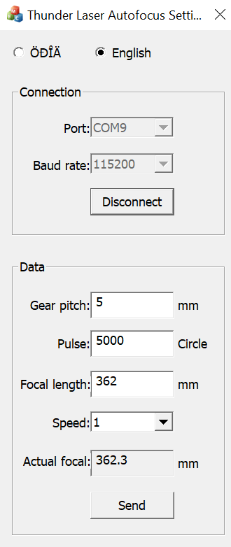
5. Lightburn 9 Point Calibration Wizard
In this step, you will perform the 9 point calibration and check for scaling. You will need a surface that you can mark on and material that you know some basic settings for. After completing the 9 point, we will check the scale of the output and adjust.
Field size settings:
Settings used to mark cardboard with UV:
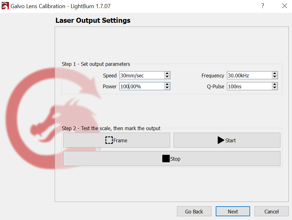
Once the marking is complete, click Next.
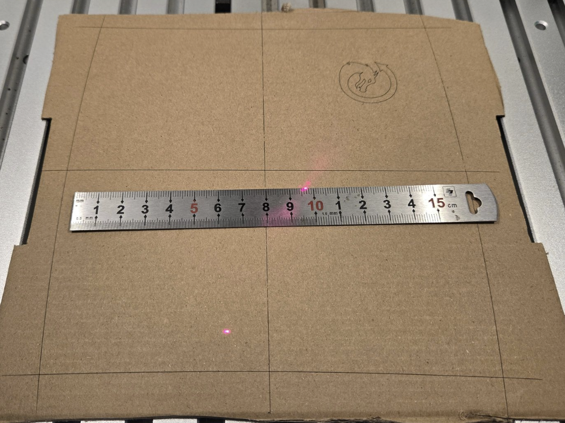
Marking result:
Lightburn will prompt for their Logo Orientation Pattern Selection:
Compare the result on the engrave and select the image that matches in the options shown.
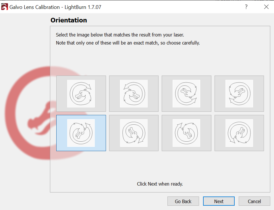
Click Next.
Measurements:
It would be good to measure all the line segments and mark them as shown for horizontal and vertical values. This will help when entering into the Lightburn prompts. Try to be as accurate as possible as this will effect how well your laser can engrave. It would also be good to mark arrows for Up and Right so that you remember the orientation.
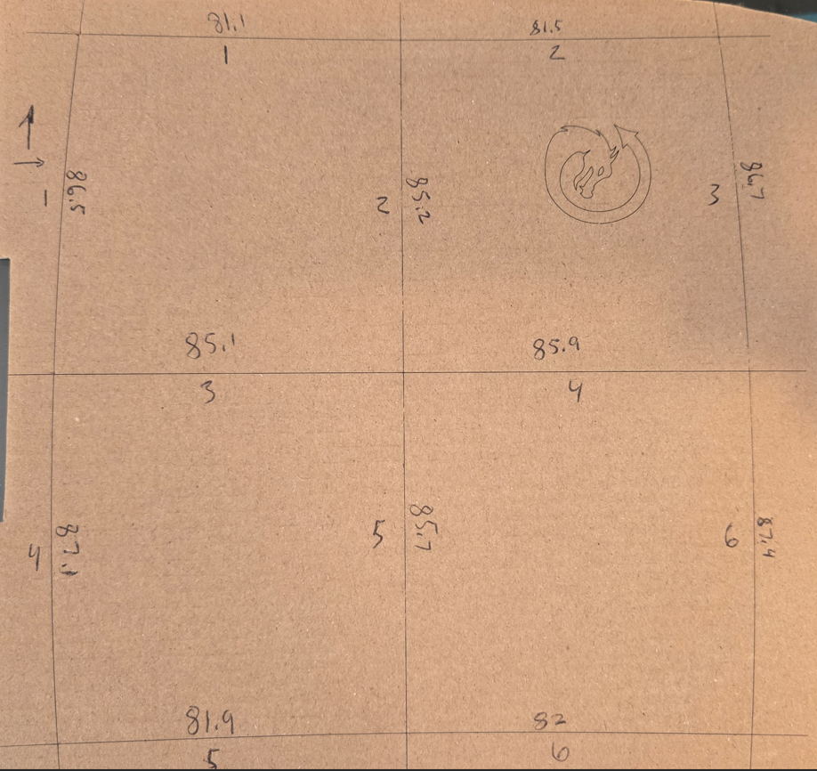
Enter in the Horizontal Measurements:
The values start at the top, Left to Right, and then down a row.
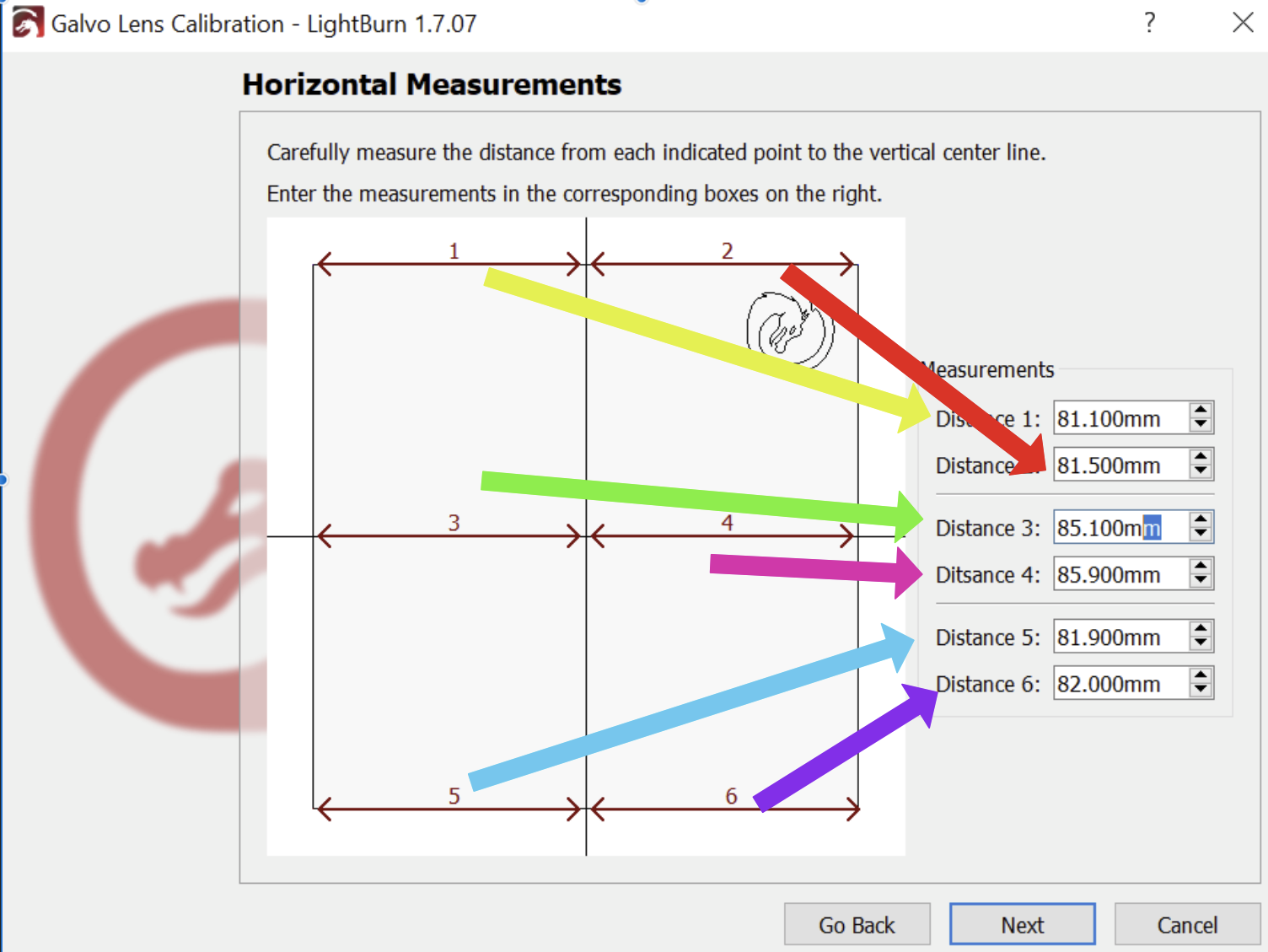
Click Next.
Enter in the Vertical Measurements:
The values start at the top, Left to Right, and then down a row.
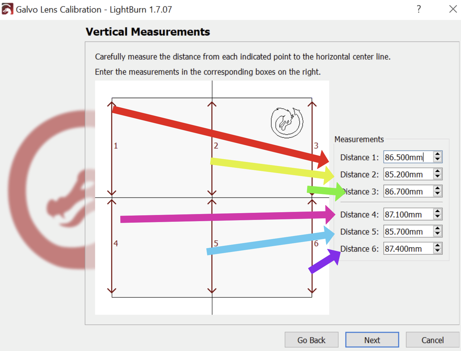
Click Next.
Results:
Lightburn will summarize the scale, bulge, skew and Trapezoid values based on the values you input. If you input an incorrect value, it will mess up the results and your engrave.
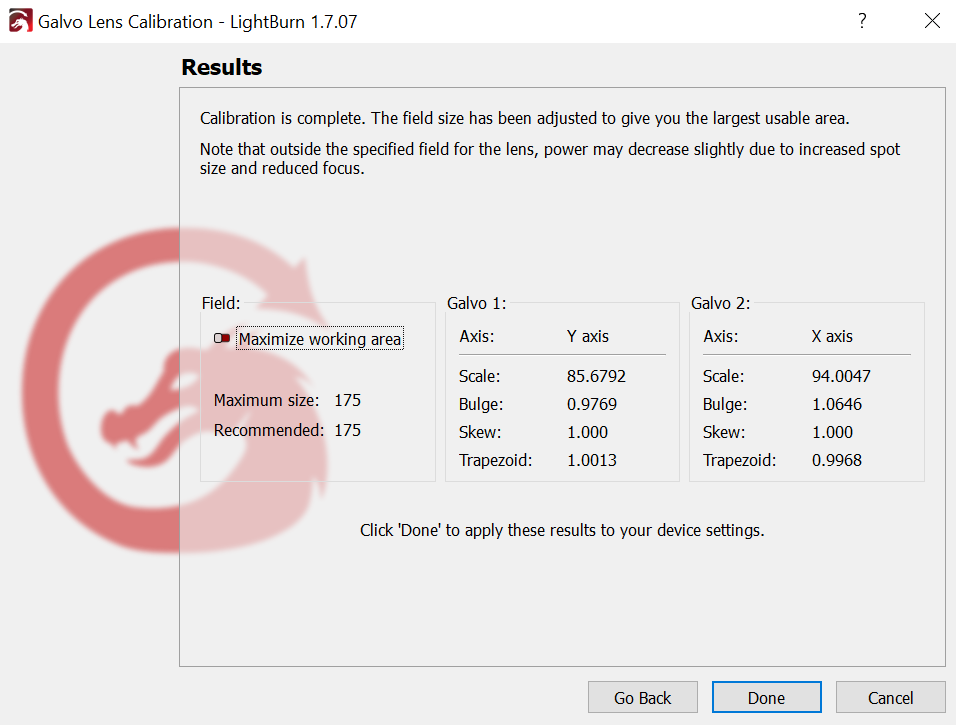
6. Scaling and Red Dot Alignment for Framing
Now that the lens should be calibrated, lets check the scaling by drawing a shape that uses a large portion of the lens space but one that you can also measure. I like to use the 100mm square since the metal ruler works well and the default input to Lightburn's scaling wizard is already 100mm.
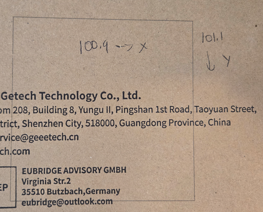
In this example, a 100mm square is scored and it actually comes out slightly larger than expected, measurements shown here:
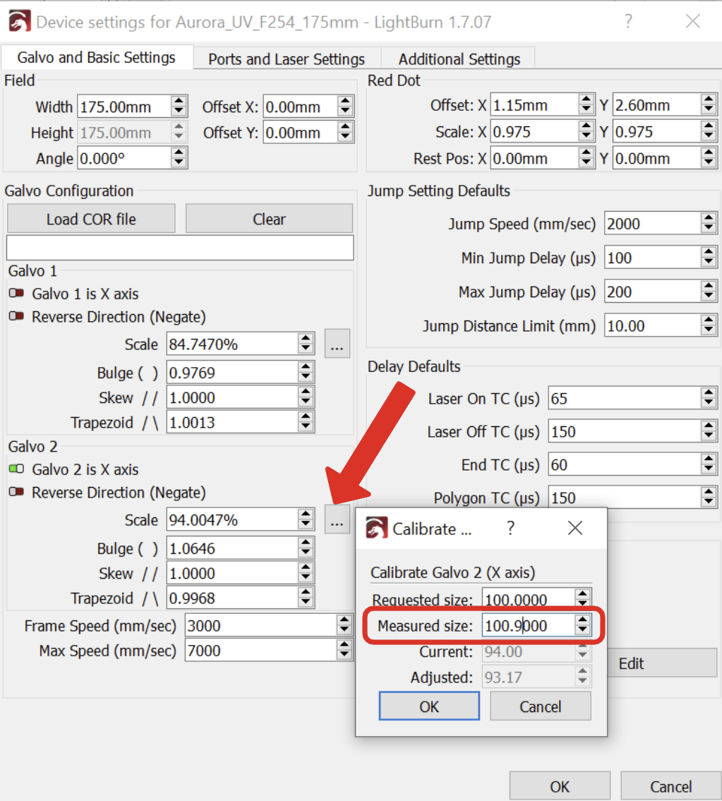
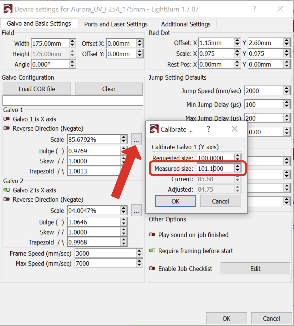
In the Galvo and Basic Settings tab in the Device Settings (edit>device settings) window in Lightburn you can enter the values to properly scale your output if needed. Lightburn automatically calculates the new Scale value based on what you enter. Pay attention so that you enter the data into the proper Galvo axis, Lightburn will caption which axis you are modifying in the wizard prompt. The X axis is the left to right and the Y axis is front to back.
| X Axis Correction | Y Axis Correction |
|---|---|
 |
 |
Check your scaling by repeating the above test until the size is perfect. Then move onto scaling the red dot frame scaling and alignment.
Red dot Framing Scale and Alignment:
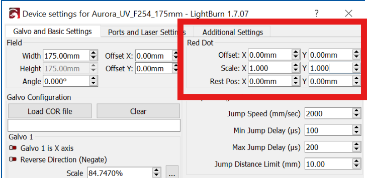
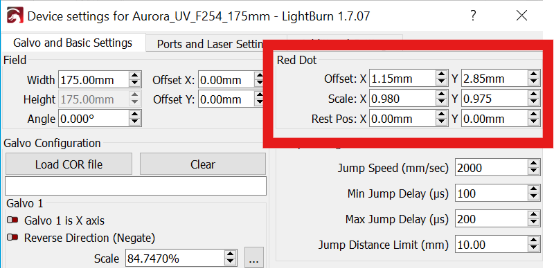
The red dot in general is a different source than the laser beam, so it can be shifted/offset from the burn spot. The software can be used to align the two while framing vs burn. In device settings, you can shift the red dot and scale it to match.
Note: When engraving, the shift of the red dot will be apparent if its on because the software adjustments cannot be applied while engraving.
The basic procedure is to mark a square on your material, then frame and adjust until your red dot traces over the border of the square you created.
The Scale function is center justified. Meaning if you adjust the value, the frame will expand in two directions equally.
The Offset function is bottom left justified. Meaning as you increase the offset, the red frame moves to the right for X or towards the back of the machine for Y.
It is suggested to adjust the Scale first, get it to the nominal size of your square and then measure the distances for X and Y from the Red Line frame to the Scored square and apply the measurements to the offset. Fine tune as needed.
| Settings | Red frame vs score line |
|---|---|
 |
After:
| Settings | After Adjustment Results |
|---|---|
 |
7. Camera Calibration (Optional)
Note: Lightburn's camera wizard is not optimized for galvos and have limited settings options so be aware of which material you choose.
In this step, you will perform the camera calibration. The calibration includes importing a preset lbcm file from your USB stick and then doing the Lightburn Camera Alignment wizard. Once complete, you should save the Camera Calibration File for your lens so that you can quickly import the file the next time you swap your lens back.
Please see this article for more information:
Aurora Camera Setup and Usage
8. Backup Your New Device Profile
After completing these tasks, it would be good to backup your profile. You have many options like Bundles or just exporting the device profile.
Please see this article for more information:
Backing Up Machine and LightBurn Settings
Still stuck?
No bots, no runaround. Talk to a U.S.-based laser tech who knows your Aurora inside out.