
Best Practices for Fill Layer Engraving and what settings to watch out for
This article covers some Best Practices for Fill Layer settings that are commonly used, misused or unknowingly used.
Fill Layer Basic Settings
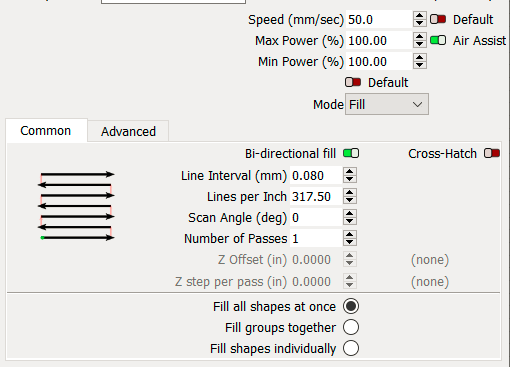
Speed: Speed at which the laser head moves in the Engrave Direction based off the Scan Angle.
Max Power: Power output while engraving
Min Power: No effect on a standard binary non image engrave. Used with the Advance Feature called the Ramp Function
Air Assist: Red\Off = Low Air, Green\ON = High Air
Bi-directional Fill: Laser engraves from the left and the right. Turning this off will double the engraving time. Turning it off can be a test for offset or mechanical issues. It is best practice to leave it on.
On

Off

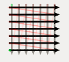
Cross Hatch: Engraves in multiple directions, 180 degree offset. Do not use this on your Thunder Laser.
Reasons: Heavy gantry, not meant to go back and forth like that for an engrave. The Y axis is speed limited to 300mms (even if you set your layer speed to 1000mms) and the Y axis does not have scanning offsets. It is all around just not advised to use on your Thunder Laser.
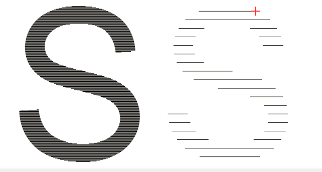
Line Interval: Spacing between engrave lines. It is your quality knob. Generally smaller intricate items need a lower interval and larger objects can have a larger interval. Quality takes time, so find the balance.
.085 vs 1.016, same letter S.
Lines Per Inch: Same as Line Interval but converted to Lines per Inch. The above picture is 300lpi vs 25lpi.
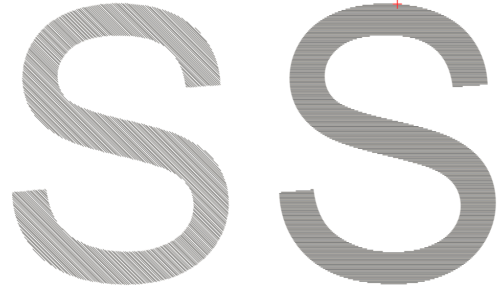
Scan Angle: Angle that the engrave function is performed. For your Thunder Laser, only use 0 or 180 degrees. Forty Five degree angle shown below vs 0 Degree.
Number of Passes: Number of times the laser will engrave over the same graphic.
Z Offset: Used for when the Z axis control is enabled. Allows the material to be moved closer or further from the laser head during the start of the layer engrave. Use caution with this setting.
Z Steps Per Pass: Used for when the Z axis control is enabled. Allows the material to be moved closer or further from the laser head for each additional pass. Use caution with this setting.
Fill Selections Section
The settings below can greatly reduce the time your job takes. The hard part about gauging which one to use is that the Lightburn time estimate can be misleading. The time estimate does not model the extend space time very well, so the user must make a judgement call as to which option is truly the best. You can also use the machine to give you a more accurate estimate.
Fill All Shapes at Once: Full width of your work space, usually heavy on traversal moves. Reduces the amount of extend time but increased traverse time can be an issue
Fill Groups Together: Lets the operator group graphics methodically to improve the flow of the engrave
Fill Shapes Individually: Each shape is engraved 1 by 1. Estimate will look nice, but the real time to engrave can vary greatly especially if the layer speed is set to 1000mms. Individual Fill benefits the most when doing slow engraves all over the workspace (Think like a USA map with state names, none on the same alignment).
So what affects the actual time the most:
Lines Per Inch = Scan Lines = Extend space\Time on each end. The more lines, the more extend time. Doing two objects individually will actually double the number of scan lines\extend space but eliminates traversal moves.

Layer Speed = The faster you go, the more space you need to extend and the more time it takes to slow down and turn around, faster layer speed is not always faster. There is a ratio between extend distance vs the actual graphic distance that needs to be considered. More on Extend Space.
Graphic Spacing = Wasted space between your graphics is traversal time. The red space between the S's is wasted time.

So take note of the Traversal time (Rapids moves) vs Total time in the estimate. The goal is to reduce both and if Traversal time is a large portion of the total estimate, then focus on reducing it.
Other techniques that can help:
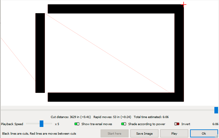
Split the design: Instead of a solid frame, make it individual halves.
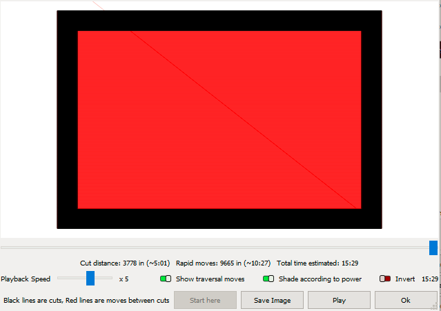
(Gap shown to show the two shape types, note that this doubles the scan line count which doubles the extend space so do not blindly trust that the time reduction from 15:29 to 6:06 is 100% accurate)
Align your graphics. Everyone tries to nest as many things as possible on their material, not realizing the time impact. The operator must choose if time or material cost is a bigger constraint. If you get your graphics misaligned, that increase the number of total scan lines which increases the extend space and time. Also note that by rotating your graphic one vs another of the exact same graphic, will yield different results when comparing the two.
Notice how the S's are not the same

Engrave as many objects as you can in the Left and Right, X direction vs the Forward and Back y-direction. This reduces the total number of scan lines and also lets the head stay at peak speed the longest. Take care to also minimize the traversal space between graphics.
Spaced too far apart:

Spaced in Y Direction:

Offset from Each other:

Fill Layer Advanced Settings

Ramp Length: Amount of ramp to the laser output when Ramp Outer Edge is enabled. Can be used to give a V carve bit look to your engraves by varying the power level as a ramped output.

Flood Fill: Not recommended generally and definitely not recommended on a Rotary Job.
Note that when flood fill is enabled, the options for the Fill Selection in the normal settings tab will be greyed out.

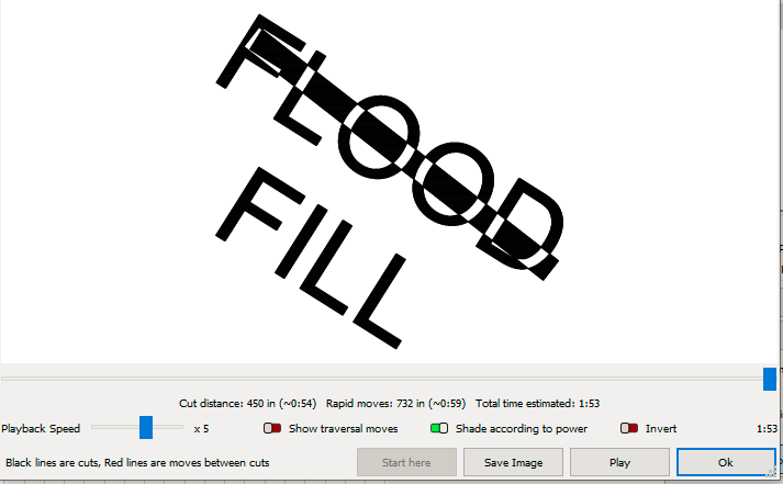
Flood Fill Also ignores some of the layer overlap settings for the fills (May be a lightburn bug and not intended):
Flood Fill On
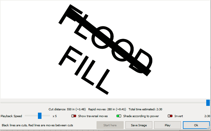
Flood Fill Off
Avoid Missing Shapes
Lightburn Forum Post About Shapes Disappearing

Use the tool to delete duplicates

Information from Lightburn
https://docs.lightburnsoftware.com/UI/CutSettings/CutSettings-Fill.html#fill-grouping
Still stuck?
Fastest response times in the industry from our US-based support team.