
Preface: This article covers different versions of the Opto-Isolator board and how those versions were wired. In order to be able to bypass your Opto-Isolator board you need to know which version you have and how it was wired at the Ruida controller. The wire colors changed so it is very important to identify what setup you have.
Quickstart Videos
Complete Procedure
Things you will need
- Small Flathead Screw Driver
- Paperclip or small jumper Wire
- To locate your Ruida Controller
- To Locate your Laser Power Supply Unit (LPSU)
- Access to the Back of the machine for Nova 35, Nova 51 and Nova 63 for the LPSU
- Access to the Right side of all Nova Machines
- Access to the Left side of the machine for the Nova 24
NOTE: always disconnect main power before attempting repairs and take good pictures before you start removing anything. Double check your wiring before powering back up
Five Wire Opto-Isolator Board Versions
If your board is an older 4 Wire version, see the section down below for the Bypass Wiring.
| Notes | Board Images |
|---|---|
|
The 5 wire Opto-isolator board comes in 2 versions as noted on the Opto Isolator itself. You must replace the opto with the exact version you have or based on the signal layout on the Laser Power Supply you plan to run. If you are swapping the LPSU out with a different series (DY, HY, MYJG, M) pay attention to the order of the signals on the LPSU input. The color of the board does not indicate version |

|
Pre-work Opto-Isolator Bypass
For newer Nova 35, Nova 51 and Nova 63 with MYJG power supply (For older versions, see down further in this article)
We need to check the wiring on your Ruida controller CN5 connector to check your wire colors. Older machines had a Brown wire on CN5 Pin 3, newer machines (around 2020 and newer) have a Grey wire on CN5 Pin 3.
Check your Controller CN5 Connector to determine which way to wire your Opto Bypass:
| Option 1 | Option 2 |
|---|---|

CN5 Pin3: LPWM1 = Brown Wire |
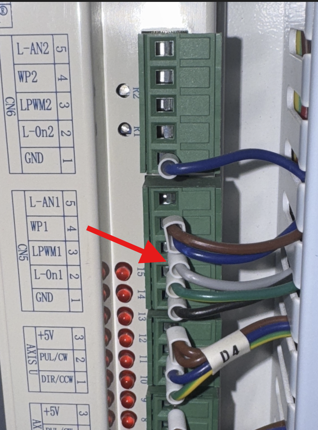
CN5 Pin 3: LPWM1 = Grey Wire |
Wiring Changes to Bypass the Opto
- Power off the machine and unplug it from the wall
- Determine which Opto Isolator Controller wiring setup you have (Images up above)
- Unplug the Opto-Isolator from the LPSU
- Take a picture of your Opto-Isolator Wiring
- With the flat head screw driver, loosen all the terminals with wires on them and remove the wires from the terminals
- With the flat head screw driver, loosen all the terminals on the left side of the Opto-Isolator to remove the 6 pin green plug off the Opto-Isolator
- Rewire the wires to the 6 pin green plug that was removed from the Opto-Isolator based on the options shown down below
- Plug the green 6 pin to the LPSU and run a job or another diagnostic and report the results to [email protected]
- If you run a project without the Opto and it is improved, you will need a replacement. You can run without the Opto installed but it is not recommended long term.
| Option 1 Before Bypass | Option 1 Bypassed |
|---|---|

|
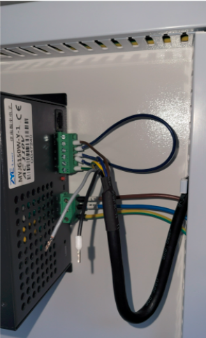
|
| Option 2 Before Bypass | Option 2 Bypassed |
|---|---|

|

|
Opto-Isolator Wiring and Bypass for Nova 24 HY-T60 Power Supply
Power supply will look like this and is located on the left side of your Nova 24:

Legacy Nova series
This is a much older version with a completely different looking Opto-Isolator. The 5v signal from the U-axis connector on the controller is not present.

Opto Isolator Wiring Schematic for Reference
| Option 1 | Option 2 |
|---|---|

|

|
Opto-Isolator Wiring and Bypass for HY-DY Series Laser Power Supply
The one on the Left has the Opto installed like the factory, the one on the right it has the Opto bypassed.

Replacement parts
Still stuck?
No bots, no runaround. Talk to a U.S.-based laser tech who knows your Nova inside out.