
Preface: This article contains information on how to check the function of the Thunder Bolt Endstops and how to adjust them.
Quick Start Video
Complete Guide
This guide aims to cover how to check a Bolt X or Y Endstop for function, how to adjust if needed and how to replace.
Note: There are many common terms for the Endstops. They may be called homing switches, limit switches, endstops, Xlimit-, YLimit-, X-Left, Y-rear etc. They all are referring to the same type of switches.
Symptoms of an Endstop Issue
- X or Y axis continues to run into the hard stops, vibrating and making a chattering noise during a startup or axis reset
- X axis moves slowly to the right during a startup or axis reset
- Y axis moves towards the front of the machine during a startup or axis reset
- Error Message for the Endstop switch being triggered when it was not expected

Bolt Endstop Function Check
The following checks will determine if the Endstop switch is functioning mechanically, electrically and if the controller is getting the signal.
X Axis Function Check
Visual Inspection
For this test we want to visually inspect the switch for damage, that the switch is still wired correctly and that the arm of the switch is still intact.
 |
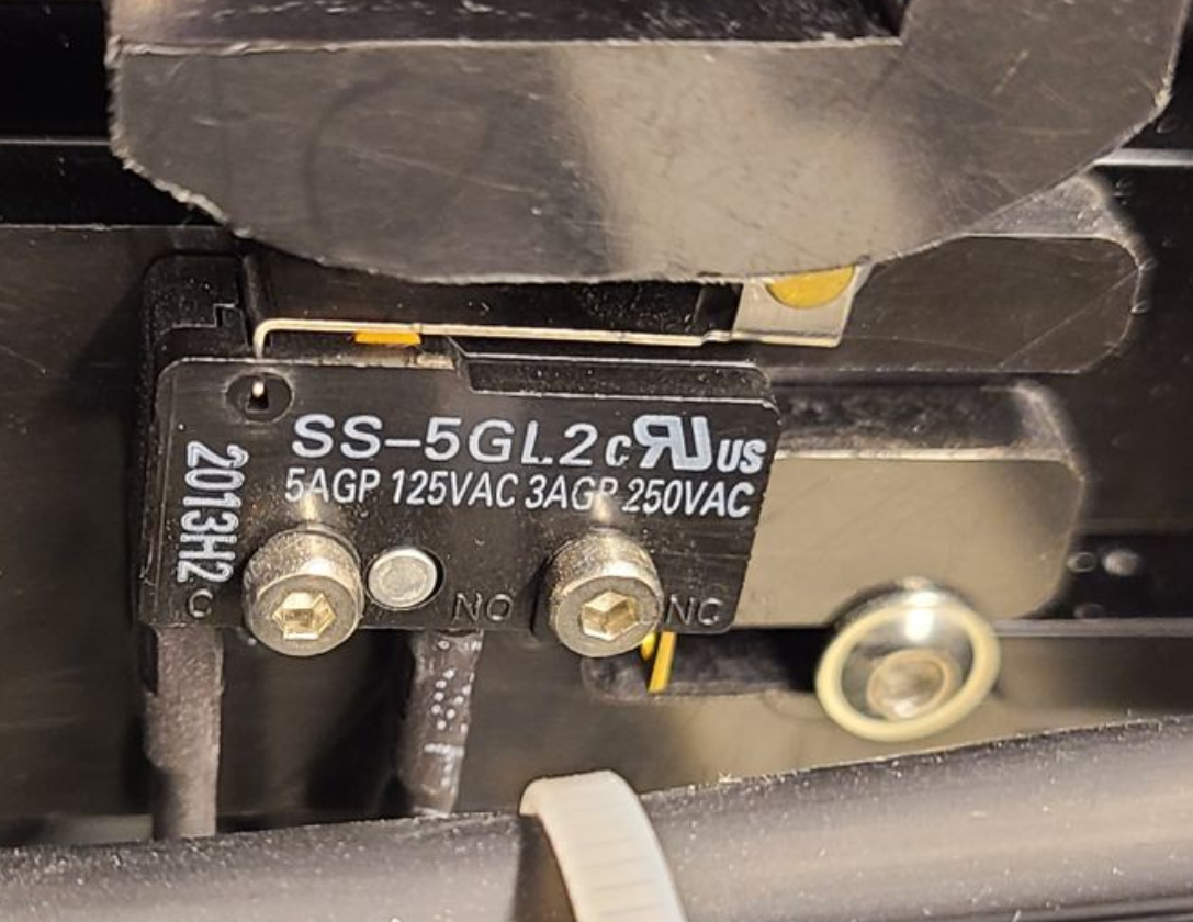 |
| X Endstop Location (Back of Moving Gantry) | X Axis Endstop Wiring (C and NO) |
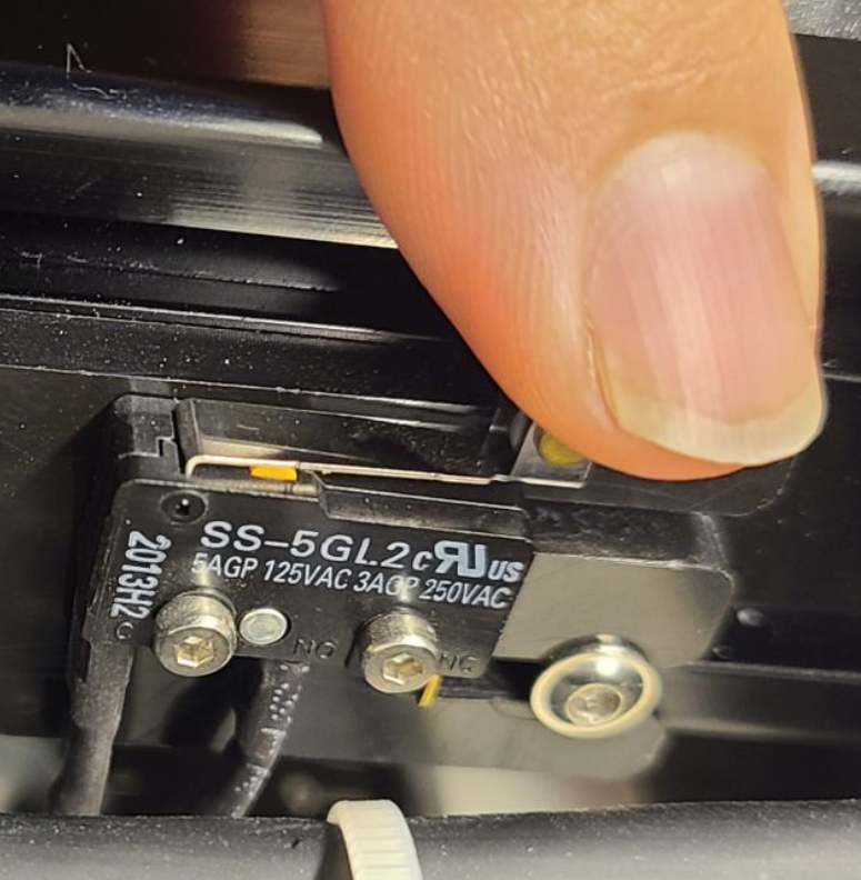
We also need to visually inspect the Activator Arm for the Endstop Switch. Make sure that the arm is not swung out of the way or too high to activate the Endstop. Adjust as needed.
 |
 |
| Activator Arm (Behind X Motor) | X Axis Switch being Activated by arm |
Test with Diagnostics Screen
Access the diagnostic screen from the MENU tab on the controller screen. Press the lever on the Endstop and observe the Red square status of X-Left Limit. As you press the lever, it should be easy and just "click". If you have to press super hard to get it to "click" then the internal part of the lever is likely broken off and the switch needs replacement.
 |
 |
| X Endstop Not Activated | X Endstop Activated |
 |
 |
| X Axis Endstop Not Pressed, Expected Result (Lid Open) | X Axis Endstop Pressed, Expected Result (Lid Open) |
Test with LED Lights on the Ruida
Access the Ruida Controller on the right side of the machine by opening the main door. Press the lever on the Endstop and observe the RED LED status for LED 1.
|
|
| X Endstop Not Activated | X Endstop Activated |
 |
 |
| X Axis Endstop Not Pressed, Expected Result LED 1 OFF | X Axis Endstop Pressed, Expected Result, LED 1 ON |
Y Axis Function Check
Visual Inspection
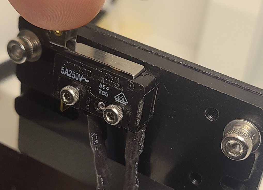
For this test we want to visually inspect the switch for damage, that the switch is still wired correctly and that the arm of the switch is still intact.
 |
 |
| Y Endstop Location (Back Right) | X Axis Endstop Wiring (C and NO) |
We also need to visually inspect the Activator Arm for the Endstop Switch. Make sure that the arm is not swung out of the way or too high to activate the Endstop. Adjust as needed.
 |
 |
| Activator Arm (Right Side Of Gantry) | Y Axis Switch being Activated by arm |
Test with Diagnostics Screen
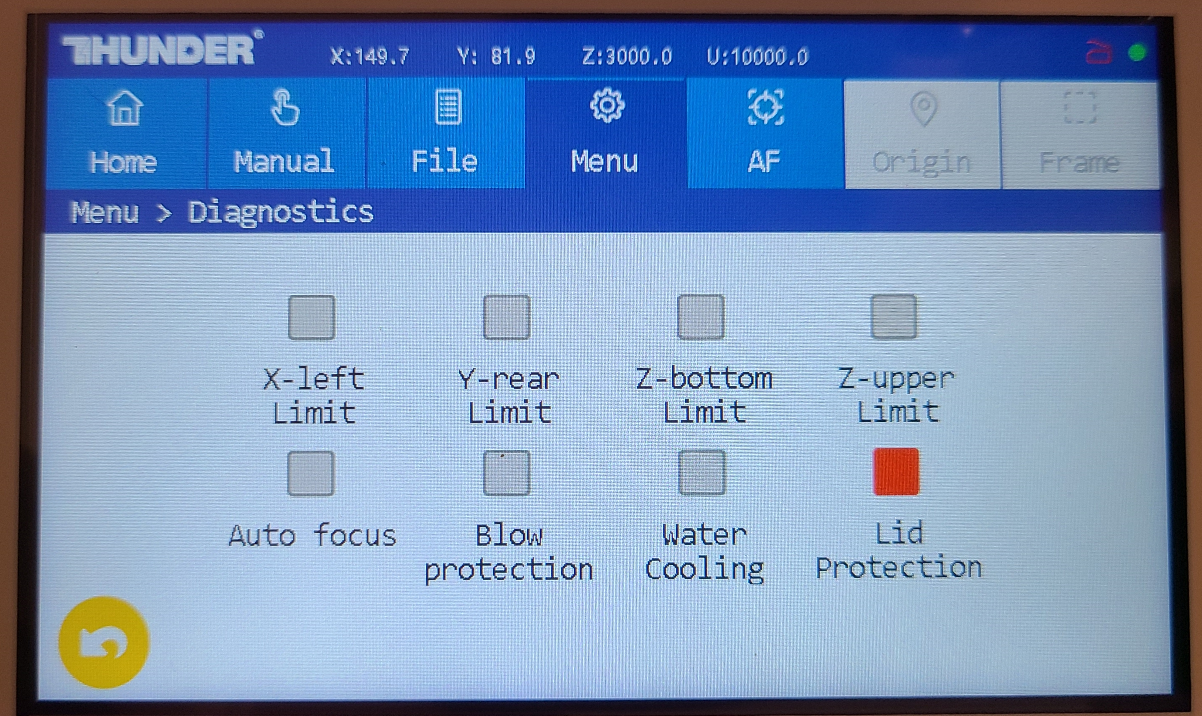
Access the diagnostic screen from the MENU tab on the controller screen. Press the lever on the Endstop and observe the Red square status of Y-Rear Limit. As you press the lever, it should be easy and just "click". If you have to press super hard to get it to "click" then the internal part of the lever is likely broken off and the switch needs replacement.
 |
 |
| Y Endstop Not Activated | X Endstop Activated |
 |
 |
| Y Axis Endstop Not Pressed, Expected Result (Lid Open) | Y Axis Endstop Pressed, Expected Result (Lid Open) |
Test with LED Lights on the Ruida
Access the Ruida Controller on the right side of the machine by opening the main door. Press the lever on the Endstop and observe the RED LED status for LED 3.
 |
 |
| Y Endstop Not Activated | Y Endstop Activated |
 |
 |
| Y Axis Endstop Not Pressed, Expected Result LED 3 OFF | Y Axis Endstop Pressed, Expected Result, LED 3 ON |
Bolt Endstop Adjustment
Adjustment is used to make sure that the Endstop switch is properly positioned and that the arm that triggers the Endstop is also properly adjusted to trigger the Endstop. You should only adjust after checking the Endstop with the information in this article about Function Checks. If the Endstop does not pass a function check, then it is pointless to adjust.
Tools You Will Need
- 2.5mm Allen Wrench for Arm and Y Axis Plate Socket Head Bolts
- 2mm Allen Wrench For X Endstop Plate Button Head Bolts
 |
 |
| X Axis Endstop Bolts | Y Axis Endstop Bolts |
Adjustment Techniques
Trigger Arm:
Endstop on Mount:
Bolt Endstop Replacement
If you determine that you need to replace a switch, the below steps should guide you through the replacement. Note that after you replace an Endstop, you should Re-Check and Adjust the Endstop to confirm that it functions properly.
Tools You Need
- 1.5mm Allen Wrench for Endstop Mounting Bolts
 |
 |
| X Axis Endstop Bolts | Y Axis Endstop Bolts |
X Axis Replacement
Power off the machine and unplug it from the wall. Slowly move the Gantry towards the front so that the X Endstop is easy to access.
-
Unbolt the Endstop using a 1.5mm Allen wrench on both bolts. Set the bolts aside.


Remove the 2 Bolts holding the Endstop to the Plate X Axis Endstop Removed from Plate Bolts to Mount the X Axis Endstop to Plate -
Remove the Endstop and then wiggle the wire terminals loose.
Note: The wires are on the C (Black wire) and NO terminals (White Wire) of the Endstop. C stands for common because it is common to both the NC and the NO terminals. NO stands for Normally Open which means the switch does not pass the Common signal unless it is pressed. If you mix up the C and NO wires, it is ok, the switch will still function. Just do not use the NC terminal.

-
Install the wires and bolt the Endstop back up. Be sure to bolt the Endstop back to the correct mounting holes.


Install wires onto the Endstop Install Endstop to Plate - Check the adjustment per the steps in the previous section of this guide.
Y Axis Replacement
Power off the machine and unplug it from the wall. Slowly move the Gantry towards the front so that the Y Endstop is not blocked by the X Motor.
-
Unbolt the Endstop using a 1.5mm Allen wrench on the two bolts. Set the bolts aside.


Remove the 2 Bolts holding the Endstop to the Plate Y Axis Endstop Removed from Plate Bolts to Mount the Y Axis Endstop to Plate -
Wiggle the wire terminals loose.
Note: The wires are on the C (Blue wire) and NO terminals (Brown Wire) of the Endstop. C stands for common because it is common to both the NC and the NO terminals. NO stands for Normally Open which means the switch does not pass the Common signal unless it is pressed. If you mix up the C and NO wires, it is ok, the switch will still function. Just do not use the NC terminal.
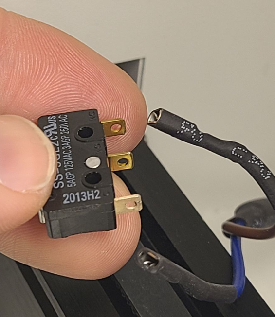
-
Replace the switch in reverse with the new switch. Install the wires onto new Switch.
It may be easier to remove the plate, then mount the switch to the plate and then the plate to the bracket.
Switch uses the upper mounting holes on the Plate.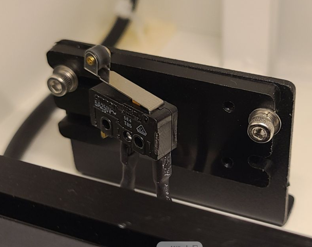


Install wires onto the Endstop Remove the plate from the Stand and install the Endstop Install Plate to Bracket - Check the adjustment per the steps in the previous section of this guide.
Where to Source Replacement Endstops
Reference Articles
What do the Red LED Lights on the Ruida Controller Mean for Nova and Odin Lasers
Still stuck?
No bots, no runaround. Talk to a U.S.-based laser tech who knows your Bolt inside out.