
Preface: This article covers the basic of replacing a rubber roller bearing on a Bolt or Odin machine.
Make sure this work is performed with the machine in a safe state. There will also be spring loaded bearing arms that can pinch. You must take the necessary precautions to prevent injury.
Quickstart Video
The quickstart video may not be all inclusive, for further details, please see the written instructions below in the Complete Guide section.
X Axis Head Bearings
Complete Guide
The below guide will walk your through removing and replacing a bearing.
X Axis Laser Head Bearings
Tools Needed:
8mm wrench

1. Identify the bearings
The X axis Laser Head has 4 bearings. Two uppers that are fixed and two lowers that are spring loaded and adjust the tension on the bearings. Please see the reference images below.
| X Axis Laser Head Upper Bearings (Fixed) | X Axis Laser Head Lower Bearings (Spring Loaded) |
|---|---|
 |

(Viewed from the back side from underneath) |
2. Head Removal
To be able to remove the head, you will require the use of both hands to unload the spring tension on the lower bearings. You will then rotate the lower part of the laser head towards the front of the machine and then lift the head up which will get the upper bearings off the X axis Gantry rail.
Push down on the spring loaded bearing arms (One on each side, do both at the same time):
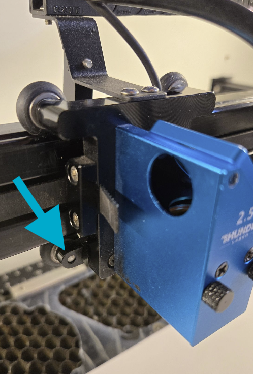
Example:
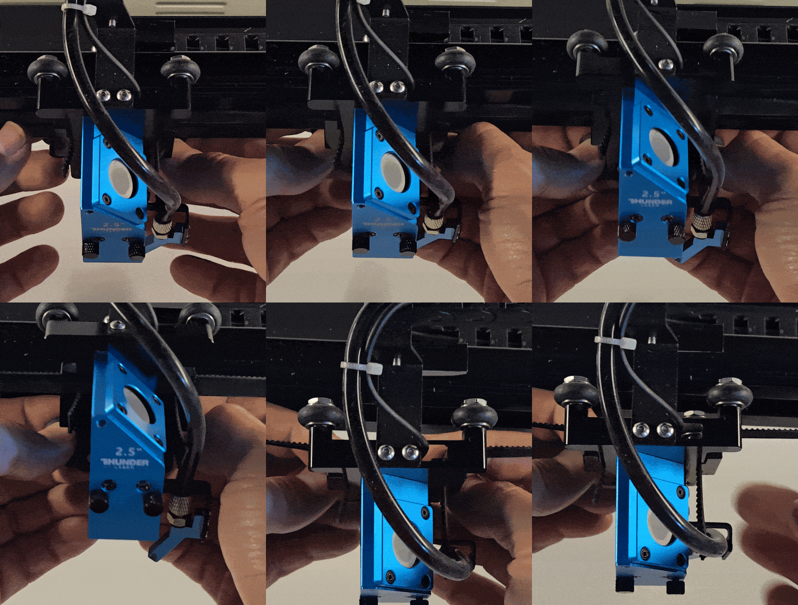
Spring load bearings at rest:
Once the head is removed and your release your pressure off the bearing arms, the bearings will go back to their resting position.

3. Bearing Swap
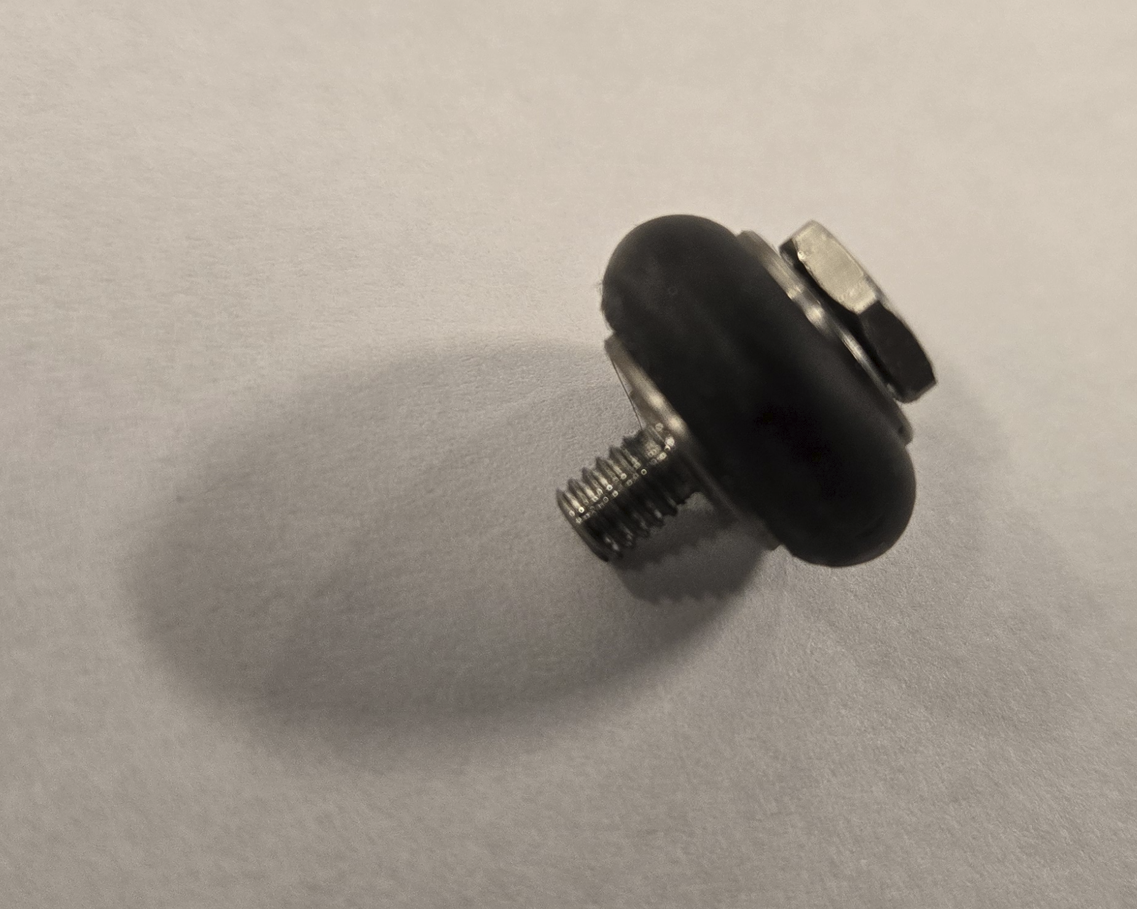
Use the 8mm wrench too loosen the shoulder bolt that is holding the bearing to the plate. The threads are right handed, but since you will be loosening from behind, the wrench will rotate to the right.

Bearing with shoulder bolt:
4. Head Re-Install
Top pop the head back on, rest the upper fixed bearings in the groove and then unload the spring loaded lower bearings and slide the lowers into place and release.
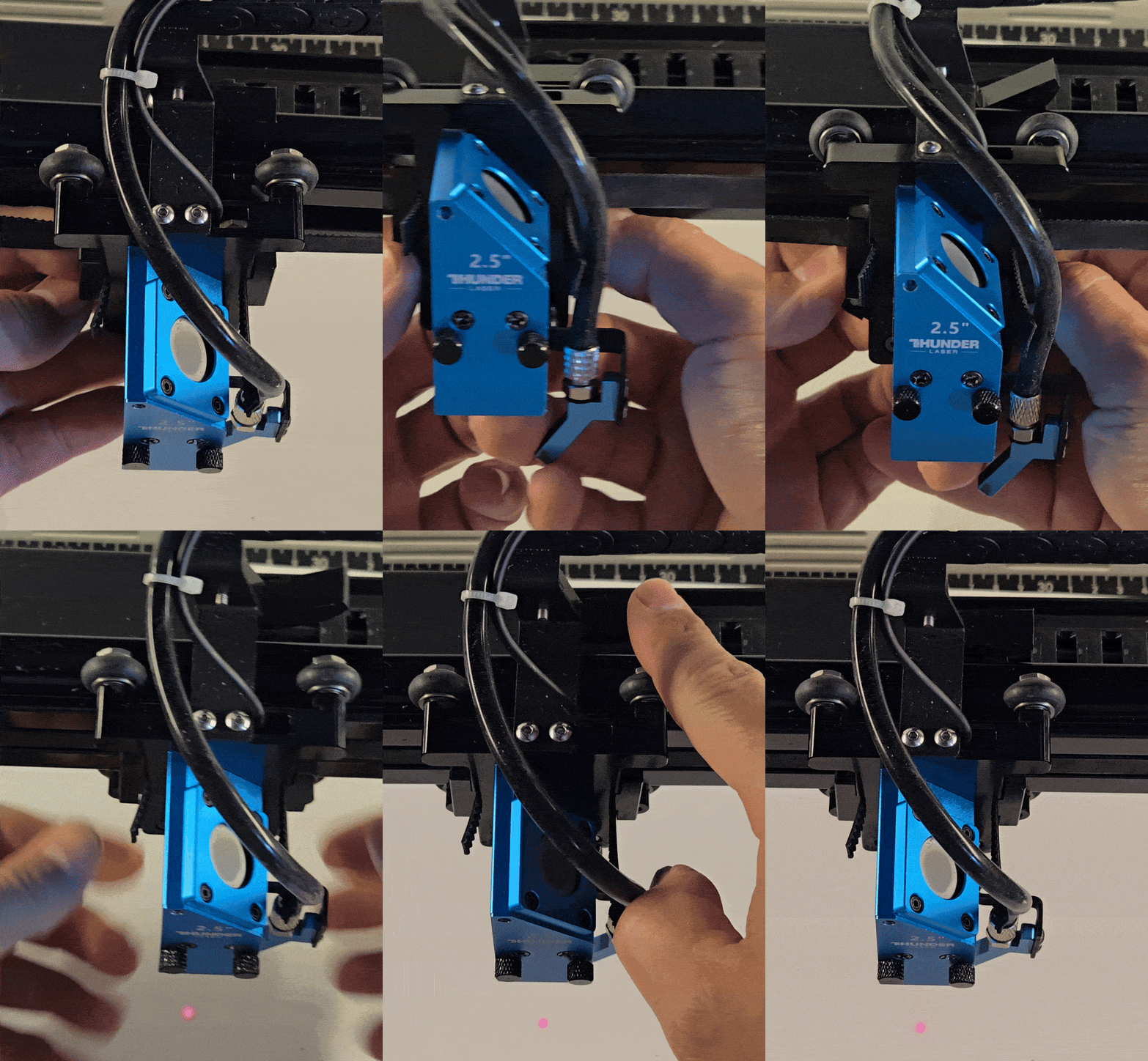
Note that the X axis endstop lever arm may get bumped out of adjustment when removing the head, be sure to inspect and put it back in its place once the head is installed back.
| X Axis Endstop Bumped out of Place | X Axis Endstop Re-adjusted |
|---|---|
 |
 |
5. Reset Machine to Home
Power up the machine to allow it to home again. Do not try to run the machine without letting it home to the back left corner.
Y Axis Trolley Bearings
The Y axis bearings will be a bit harder than the X axis since you have two sides of the gantry to deal with and both have fixed and spring loaded bearings. There are times where a second set of hands would be helpful, especially when high levels of dexterity is required.
Tools Needed:
8mm wrench, 2mm and 2.5mm Allen wrenches and 2 protective cloths

1. Identify the bearings
The gantry has eight total bearings. There are four on the left side trolley (pair of inboards and pair of outboards) and four on the right side trolley (pair of inboards and pair of outboards). The outboards on the left side are a little harder to get to due to the mirror mount and drag chain components. The inboard bearings are Fixed bearings where as the outboard bearings are on spring loaded arms.
| Left Side Inboard | Right Side Inboard |
|---|---|
 |
 |
| Left Side Outboard | Right Side Outboard |
|---|---|
 |
 |
2. Y Axis Gantry Bearing Swap Process
The bearing swap for the inboard will be easy. If you plan to do the outboard at the same time then you should do the outboard first and then the inboard. This guide will be written in that order, so all 8 bearings. If you will only be doing the inboard, you can skip the additional steps for the outboard bearings. You will be working with spring loaded arms, there will be pinch hazards so take appropriate precautions. Once the gantry is removed from the rails, the arms and springs can be unloaded prior to bearing removal.
I. Remove inboard bearings
Use the 8mm wrench to remove the 4 Inboard bearings from the gantry (2 on the left trolley and 2 on the right trolley)
| Left Side | Right Side |
|---|---|
 |
 |
II. Remove belts from trolley plates
Using the 2mm Allen head, loosen the two bolts that hold the Belt Retainer bar to the trolley plate. Go slow to avoid stripping when loosening the bolts.
| Left Side | Right Side |
|---|---|
 |
 |
There is a bar that holds the belt tight that is slid into the trolley plate. At first it may feel stuck if you just try to push down. Instead, try sliding the bar and belt out of the trolley plates. You may even have to push the bar a little like a Jenga(R) block.

Once the block is removed for the first time, it is easier to remove and reinstall.
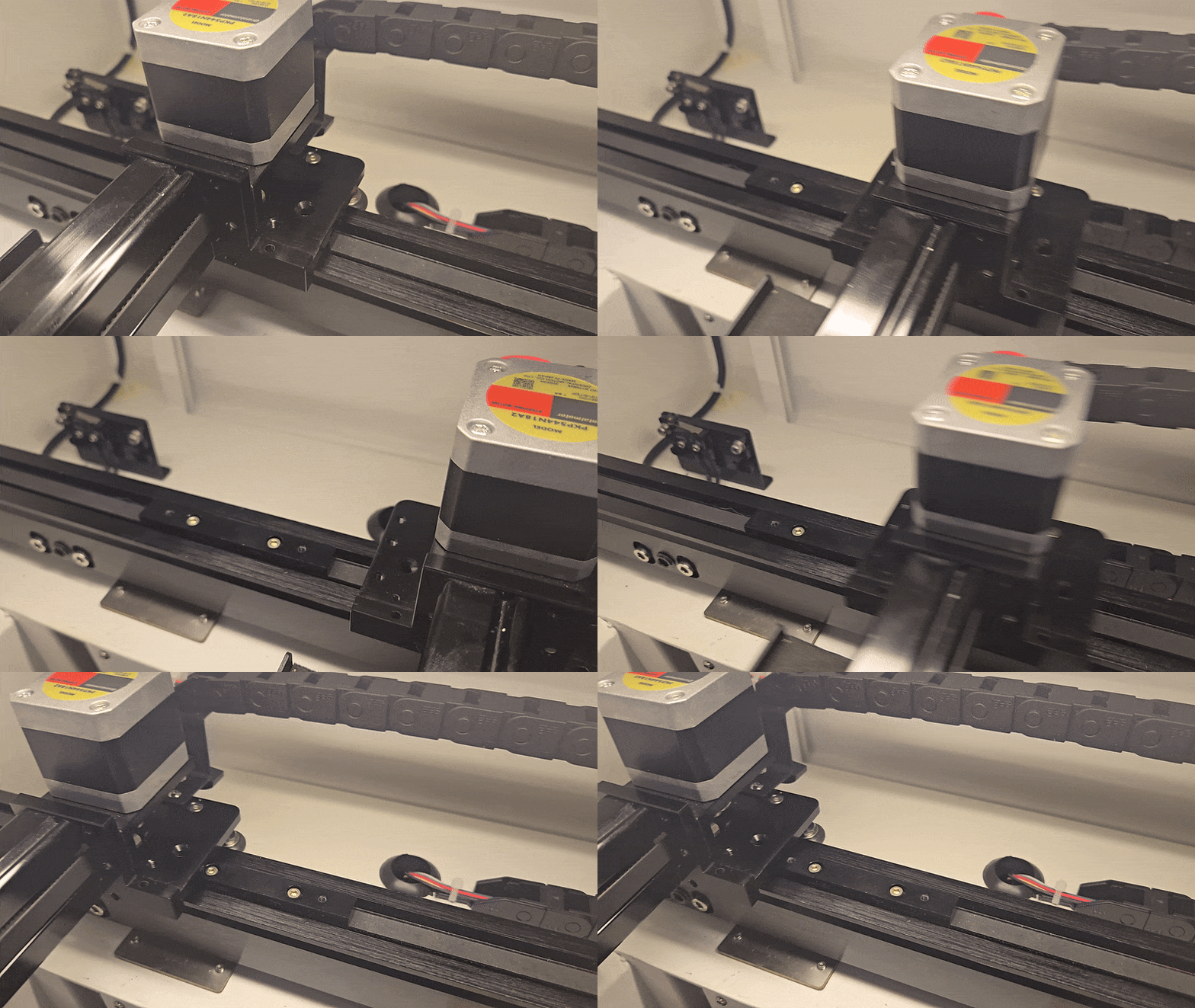
III. Lift gantry off the rails
You will need some dexterity here. Both sets of spring loaded bearings will need to be depressed to allow the bar to tilt up and off the rails. It would be good to put something between the gantry bar and the rails to limit damage. Keep in mind that the gantry will still be connected to the drag chains so it is not free to move about everywhere. Just tilt up the gantry and then lay it on its side on the rails.
How to depress the lever arms:
This shows how to press the lever arms so that the bearings are unloaded out of the channels in the side rails. When removing the gantry, using 2 fingers per side, 1 per lever arm, was most ideal (middle and ring finger).

Technique to depressing both sets of springs and Lifting the gantry off the rails:
Open the right hand side door and reach through it for the right side.
For the left side, reach through the open lid, not left hand door.
You will be hugging the machine essentially. But be sure to depress all the spring arms so that you can easily lift the gantry assembly up.
Once the assembly is free, you can rotate and let it rest on the guide rails.

IV. Remove Lever arms and then the Outboard bearings
Flip up the gantry and use the 2.5mm Allen Wrench to remove the Lever Arm retaining bolt. Be careful as there are small washers on the bolts. Set aside for safe keeping.

Use the 8mm wrench to loosen the bearing bolt and remove the bearing from the Lever Arm

Disassembled Lever Arm

V. Reinstall New bearings
Install the new bearing with the shoulder bolt to the arm. Be sure to note the orientation of the arm when mounting the bearing.
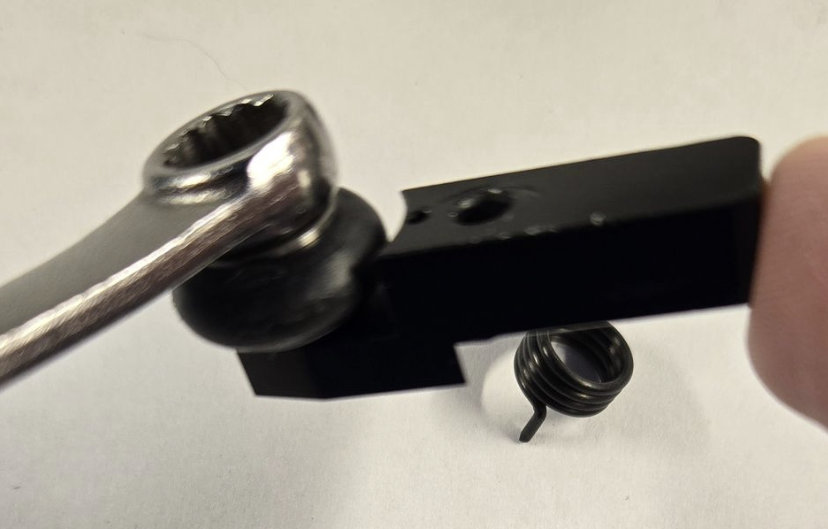
Install the Spring so that the post lines up with the hole in the Lever Arm

Slide the Lever Arm Assembly back onto the post it was removed from, be sure to line up the spring Post with the hole in the trolley plate

Reinstall the retaining bolt and washer
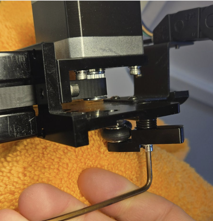
VI. Install Gantry in reverse
Pop the gantry back on the way it came off. You will need to depress the lever arms so that you can gently place the gantry and then release the lever arms so that the bearings are in the slot of the rail. This will be the hardest part of the project. You will need to be gentle so that the new bearings are not scuffed and to prevent scratching the aluminum coating.
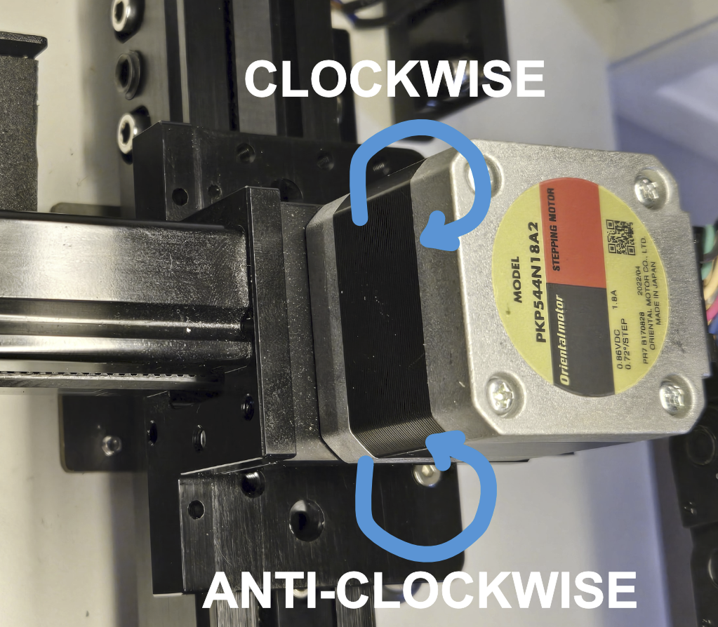
Need to keep in mind how the bearing Lever arms should rotate from their resting position to be in their proper tensioned position without damaging the spring.
| Left Side | Right Side |
|---|---|
 |
 |
Once the gantry is back on, reinstall the 4 bolts that hold the belt bracket to the trolley plates (2 per side) using the 2mm allen wrench.
VII. Reinstall New inboard Bearings
Use the 8mm wrench to install the new bearings. When installing them, have the bearing set in the rail groove so that the bolt will be able to thread into the trolley plate.
| Correct | Wrong |
|---|---|
 |
 |
Also, when installing the Y Axis bearings, stay between these areas on the rail, the hardware that protrudes can make it harder to install/turn the wrench.

3. Reset Machine to Home the Axes
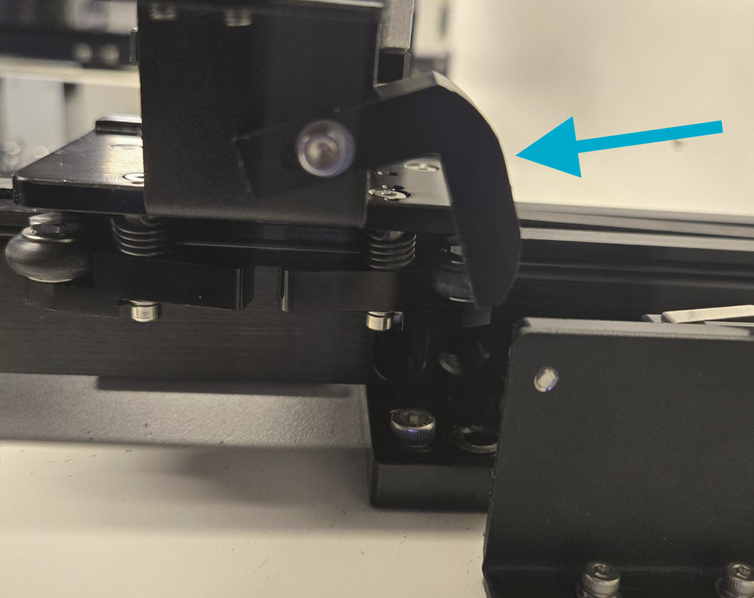
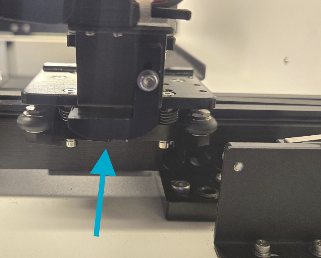
Double check before powering back up that the Lever Arm for the Y Axis endstop is back in place, it may have shifted as the gantry was tilted around and worked on.'
| Out Of Place | Much Better Position |
|---|---|
 |
 |
Power up the machine to allow it to home again. Do not try to run the machine without letting it home to the back left corner.
After you complete the bearing swap on the Y Gantry, it would be good to check that your gantry is square and your mirror alignment is good to go.
Reference Links
Still stuck?
No bots, no runaround. Talk to a U.S.-based laser tech who knows your Bolt inside out.