
MAX Fiber Laser Source Guide
Maxphotonics MFSC-1000X / MFSC-1500X (G4.0) continuous-wave fiber laser · as fitted to Thunder AccuMetal 1500 W machines
The laser source generates the beam and sends it down the fiber to the cutting head. It is water-cooled, sealed and has no user-serviceable parts. This guide covers what an operator needs: panels, specs, cooling, start-up, connector care and the source's own error list. Full alarm handling is in the companion AccuMetal Errors and Alarms guide.
| Quick facts | MFSC-1000X | MFSC-1500X |
|---|---|---|
| Output power | 1000 W | 1500 W |
| Wavelength | 1080 nm (1070–1090) | 1080 nm (1070–1090) |
| Power adjustment | 10–100% | 10–100% |
| Supply | 200–240 VAC single-phase | 200–240 VAC single-phase (360–440 VAC 3-phase optional) |
| Input power at full output | 3.2 kW | 5.0 kW |
| Recommended breaker | 32 A, close to the source | 32 A, close to the source |
| Cooling water flow | ≥10 L/min (2.6 gpm) | ≥15 L/min (4 gpm) |
| Weight | 32 ± 2 kg (71 lb) | 36 ± 2 kg (79 lb) |
Inside:
- Front panel
- Back panel
- Specifications
- Cooling and environment
- Start-up and control modes
- Monitoring software
- Fiber connector (QBH) care
- External control (CTRL) pinout
- Error list, service and warranty
1. Front panel
Front panel controls and lights
| # | Item | What it does |
|---|---|---|
| 1 | ALARM light | Lights red on a fault |
| 2 | ACTIVE light | Lights green when the laser is normal |
| 3 | POWER light | Source has power |
| 4 | START button | Hardware start signal for external-control mode |
| 5 | Key switch (OFF / ON) | Main power switch for the laser |
| 6 | Emergency stop | Cuts laser emission immediately |
2. Back panel
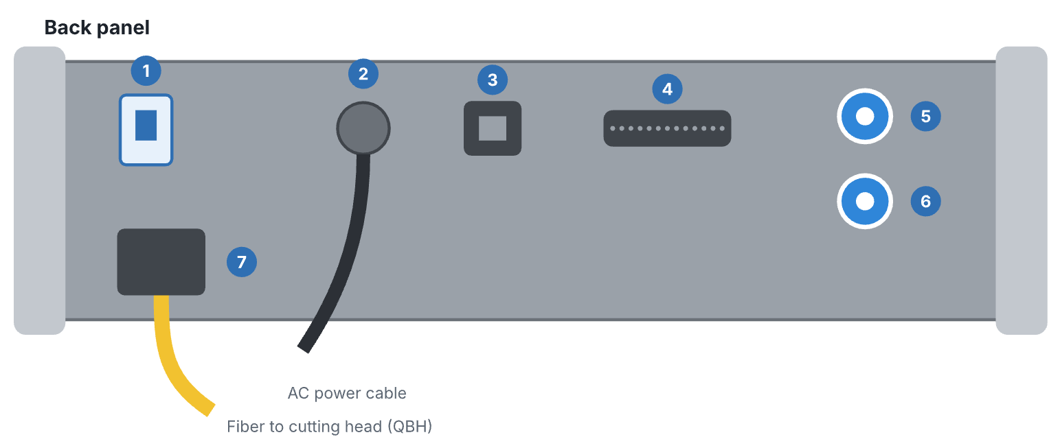
Back panel connections
| # | Item | What it does |
|---|---|---|
| 1 | POWER | AC power switch |
| 2 | AC input | 200–240 VAC (1500X: 360–440 VAC optional) |
| 3 | ETHERNET | Link to the monitoring software |
| 4 | CTRL | DB25 external control connector (to the machine controller) |
| 5 | WATER OUT | Cooling water return |
| 6 | WATER IN | Cooling water supply |
| 7 | OPTICAL OUTPUT | Delivery fiber to the cutting head |
3. Specifications
Optical
| Parameter | Value |
|---|---|
| Operating mode | Continuous wave (CW) or modulated |
| Polarization | Random |
| Output power | 1000 W (1000X) · 1500 W (1500X) at 100% CW |
| Power tuning range | 10–100% |
| Wavelength | 1070–1090 nm, nominal 1080 nm |
| Spectral width (3 dB) | 3–5 nm |
| Power stability | ±1–1.5% over 1 h · ±2–3% over 24 h |
| Beam quality (BPP) | 1.5 mm·mrad (50 μm fiber, QBH) |
| Switching on / off time | 50–100 μs (10–90%) |
| Modulation rate | Up to 20 kHz |
| Red guide laser | 200 μW |
| Delivery fiber | 50 μm core · 1000X: 10 m (5, 15 optional) · 1500X: 15 m (5, 10 optional) |
| Minimum fiber bend radius | 200 mm (8 in) |
| Output connector | Standard QBH |
General
| Parameter | Value |
|---|---|
| Operating voltage | 200–240 VAC (nominal 220) · 1500X optional 360–440 VAC |
| Input power at 100% | 3.2 kW (1000X) · 5.0 kW (1500X) |
| Ambient temperature | 10–40 °C (50–104 °F) |
| Relative humidity | 10–85%, non-condensing |
| Storage temperature | −10 to 60 °C (14–140 °F) |
| Dimensions (W × D × H) | 482.6 × 550 × 133 mm (19 × 21.7 × 5.2 in), 19" rack width |
| Weight | 32 ± 2 kg (1000X) · 36 ± 2 kg (1500X) |
4. Cooling and environment
Two loops: cool water for the source, room-temperature water for the head
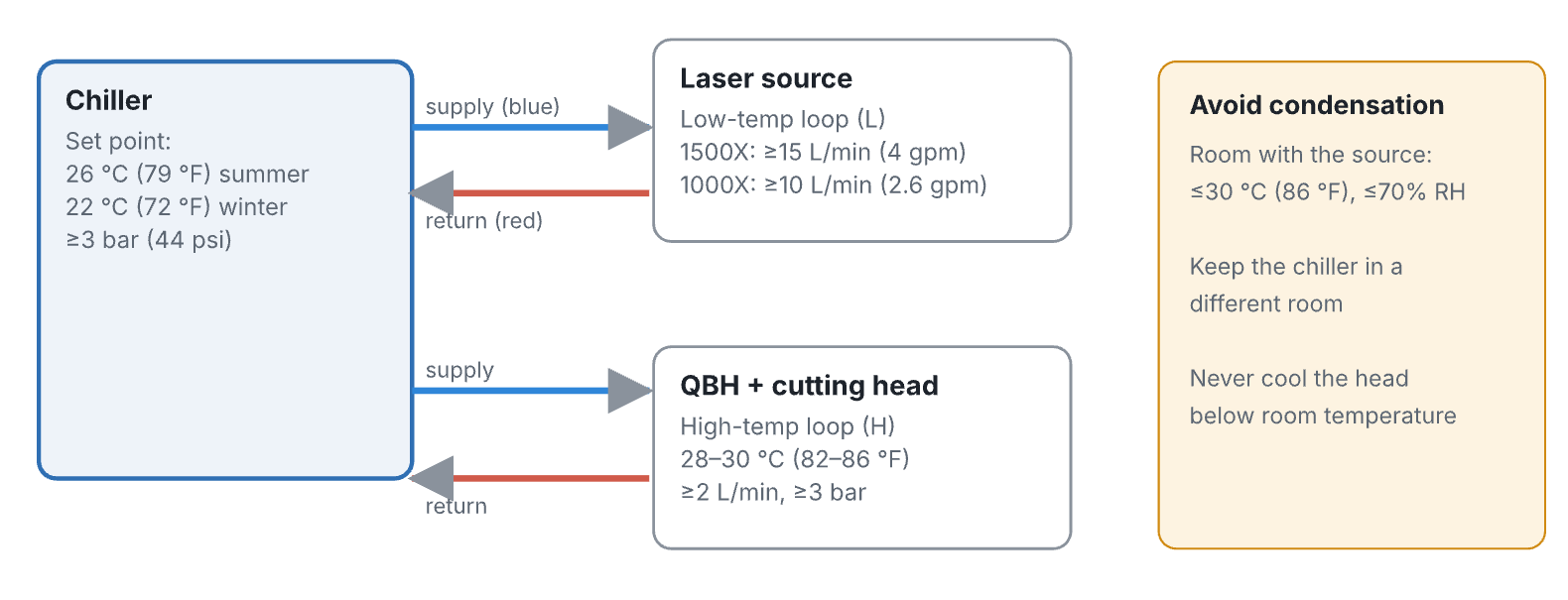
Chiller loops on the AccuMetal: L = laser source, H = QBH and cutting head
| Requirement | 1000X | 1500X |
|---|---|---|
| Chiller set temperature | Ambient ≥30 °C: 26 °C · below 30 °C: 22 °C | Same |
| Water pressure | ≥3 bar (44 psi); main-line drop ≤0.5 bar | Same |
| Water flow (source) | ≥10 L/min | ≥15 L/min |
| Chiller cooling capacity | ≥2.5 kW | ≥3.5 kW |
| QBH / head loop | ≥2 L/min, ≥3 bar, 28–30 °C; 6 × 4 mm tube; head drop ≤1.5 bar | Same |
- Change the water and filter every month. Use distilled or deionized water.
- Freezing weather: switch to a glycol antifreeze mix before temperatures reach 0 °C (32 °F). Don't overdose; too much antifreeze cuts heat transfer. Go back to distilled water and a new filter after winter.
- Long shutdowns: blow the water out of the inlet and outlet lines with clean air so nothing freezes inside.
- Hose colors: blue = supply, red = return. Swapped hoses trigger a water-flow or pump-temperature alarm.
5. Start-up and control modes
On the AccuMetal, the machine's laser switch powers the source and chiller together (see Startup and Shutdown). The source itself starts in this order:
- Chiller running and at temperature.
- End cap removed from the collimator / QBH, and its window clean.
- Emergency stop released.
- Source power on.
- Key switch to ON.
- Press START (external-control mode).
| Mode | Controlled by | Used for |
|---|---|---|
| Internal control | The MAX monitoring software | Checking the source and measuring power |
| External control | The machine controller via the CTRL cable: enable, modulation, 0–10 V power, START | Cutting (normal AccuMetal operation) |
Commission and align at low power first, then raise power step by step.
6. Monitoring software
- Install the MAX fiber laser monitoring software (and .NET 4.6 if Windows needs it) from the Maxphotonics download center.
- Connect the source's ETHERNET port to the PC and power the source.
- Open the software, choose IP2, enter the source IP 192.168.0.178 (default) and click Login. Sources with an RS232 port use COM and the COM port number instead.
The software's pages: Monitor (status lights, power, water flow, temperatures, back-reflection), Charts, Decryption (enter unlock codes from support), and Log (alarm history). On the AccuMetal a login window may open at start-up; closing it doesn't affect cutting.
7. Fiber connector (QBH) care
A dirty or damaged QBH window can burn the connector and the cutting-head optics, and that damage isn't covered by warranty. Inspect it every time the connector is removed.
Inspection and cleaning sequence
You need: powder-free gloves or finger cots, lint-free optical wipes and swabs, optical-grade anhydrous ethanol (over 99.5%), oil- and water-free compressed air, a microscope and a light.
- Turn the key switch to OFF and remove power.
- Take off the black outer sleeve but leave the white inner cap on. Clean the outside of the connector with optical cleaner, wipe and blow dry.
- Set the connector in the microscope holder, remove the white cap and focus on the protective window.
- If you see dirt: wet a swab with a few drops of alcohol (shake off the excess), place it on the dirt and gently push the dirt to the edge of the window. Repeat with fresh swabs until clean, then check again.
- Refit the cap and sleeve, or insert the connector into the cutting head straight away and lock it.
8. External control (CTRL) pinout
For technicians. The CTRL port is a DB25 connector to the machine controller.
| Pin | Wire | Signal | Specification |
|---|---|---|---|
| 18 / 5 | Red / red-white | Enable input + / − | High 20–24 VDC, low 0–5 VDC, 5–15 mA |
| 17 / 4 | Black / black-white | Modulation input + / − | High 20–24 VDC, low 0–5 VDC, 5–15 mA |
| 16 / 3 | Yellow / yellow-black | Red guide light + / − | High 20–24 VDC, low 0–5 VDC, 5–15 mA |
| 15 / 2 | Green / green-white | Analog power (DA) + / − | 0–10 V sets power: 1 V = 10%, 10 V = 100% |
| 14 / 1 | Brown / brown-white | Fault output 1 / 2 | Dry contact: closed = fault, open = normal; ≤30 VDC, ≤100 mA |
| 19 / 6 | Blue / blue-white | Interlock + / − | Shorted = laser can emit; open = locked, no emission |
| — | Green-yellow | Ground | Protective ground |
Laser output follows the enable signal, then the modulation signal, at the power set by the analog voltage.
9. Error list, service and warranty
| # | Alarm | Meaning | What to do |
|---|---|---|---|
| 1 | Internal light-path warning | Output is low compared with the command | Check for low modulation frequency, peak power or cutting power settings |
| 2 | Water-cooling plate overheat | The source's cooling plate is too hot | Check the chiller set temperature meets the table in section 4 |
| 3 | Emergency stop | The E-stop is pressed | Release it and restart; contact support if it persists |
| 4 | Water flow / pump temperature | Flow or pressure problem in the chiller or source | Check chiller pressure, look for swapped inlet and outlet hoses, clear lines with an air gun |
| 5 | Overcurrent | Internal current too high | Check the 0–10 V analog signal isn't over its limit; otherwise contact support |
| 6 | Overvoltage | Supply voltage out of range | Check the mains voltage is within spec |
| 7 | QBH installation | The QBH isn't seated in the cutting head | Seat and lock the connector; contact support if it persists |
| 8 | Encryption expired | ALARM and ACTIVE flash red and green | Contact Thunder Laser support for a new code |
Service
- There are no user-serviceable parts. All repairs go through Thunder Laser support, who coordinate with Maxphotonics.
- Don't return a source without an RMA. Keep proof of any shipping damage for the carrier claim.
Warranty limits (summary)
Maxphotonics covers defects in materials and workmanship for the contract period. Not covered: opened or modified sources; misuse, neglect or accidents; use outside the specifications or this guide; damage from user software or interfaces; improper installation or maintenance; fittings and fiber connectors. Report defects within 31 days of finding them.
Summarized from the Maxphotonics MFSC 1000X–1500X (G4.0) CW Fiber Laser Series user manual. Specifications are Maxphotonics'; the official manual and the source's nameplate govern. Thunder AccuMetal 3000 W machines use a different source model.
Still stuck?
Fastest response times in the industry from our US-based support team.